Hose fittings:
- 1/4" male pipe to 3/8" ID hose barb. Builder's Square Waxman part number
07-811
- 1/2" hose barb to 3/8" hose barb (Builder's Square Waxman part number
07-832) , or make your own using:
- 3/8" pipe double female union
- 3/8" male pipe to 1/2" hose barb
- 3/8" male pipe to 3/8" hose barb
- Washers - 3/16" (you need about 10). 10mm washers also work if you can't
find 3/16".
- Fuel Line Disconnect Tool - 5/16" and 3/8" KD Tools #3321. The fuel
lines use a quick connect fitting that requires a special tool available at
any normal auto parts store. The tool actually consists of a set of quick
release tools for newer A/C and fuel fittings. A 6 piece set from JC
Whitneys for about $7 (p/n 89XX0707U) which works great.
- Drill bit - 7/8" or larger, or a comparably sized hole saw (used to
drill into the covers for the fuel lines).
- Assorted files
- 1/4" to 5/8" fitting for the intake to fit the new power brake booster
hose which is smaller than stock. ~$2.
- 1/4" size brake booster valve to go onto the brake booster. ~$2.
- OR Arizona Speed and Marine offers made-to-fit covers for $165 that are
polished aluminum. This will save many of the modifications listed below for
a bit of extra cash.
If you are using the plastic Corvette valve
covers, you will also need the following:
- Valve covers, old P/N 10108605 and 10108606, new P/N 12552321 and
12552322, $80 each (net)
- Cap Assembly, P/N 12554955, $3LI>
- Valve Stud, P/N 10108674 (you need eight), $???
- Bolts, P/N 10108675 (you need eight), $???
The valve cover gaskets come with the valve covers, and the crankcase
breather adapter grommet comes with the RH valve cover. You need to trim
crankcase breather hose to fit new grommet.
There are also some new injector covers available that are used on the
Corvette LT4 engines. You will still need all of the other parts from the
normal install, above, except for these different covers. The only difference
is that they have red lettering instead of the normal black letters:
- LT4 Injector covers: P/N 12552432 & 12552431, about $20 each
- LT4 Throttle Body Plate (called AIR COVER): P/N 17113211, about $10
For those of you with late '95s and '96s, GM changed the design of the
pipe/check valve/rubber hose setup over the RH valve cover to a straight pipe
design, connected to the check valve, then to the rubber hose, which now makes
a u-turn over the cover. The previous design had a small u-turn pipe that
connects to the check valve and then a 90 degree rubber elbow hose. This
design agreeably looks better than having a rubber hose run across the valve
covers. Here are the part numbers for the older, better looking design:
- 10231681 - Pipe Assembly - retail $9.10
- 10217106 - Connector - retail $3.40
- 22040805 - Valve - around $15-$20
- A brass flanged connector that converts a 7/8" male connector to a 1/2"
male connector, or female on the 7/8" side and male on the 1/2" side.
Note that if you order your parts from Bob at World Parts, you can just order P/N
N800. $39.95, to get the entire injector cover kit set. This includes all of
the GM parts required.
- Before you get started, decide if you will be replacing the valve covers
with the magnesium units from the 87-92 Vettes, the plastic ones from the
93+ Vettes, or leaving them stock. The Vette covers will prevent rusting and
quiet down the noisy LT1 valvetrain. The magnesium covers should be coated
to prevent staining (e.g. Jet-Hot). If you are using the stock stamped steel
valvecovers, then you should use the RH injector cover from the '92-'93
Corvette application (P/N 10224936) instead of the RH cover listed above.
This is because the stock valvecovers have the crankcase vent tube on the
top of the cover, as did the Magnesium LT1 valvecovers used on the '91-'92
Corvette. The RH injector cover for those years has a clearance notch for
the crankcase vent hose to pass through. You should always use the LH
injector cover from 94+ Vettes.
- Because the Corvette brake vacuum hose is smaller in diameter than the
stock hose (11/32" ID compared to 1/2" ID), you will need to change the
brake vacuum fitting in the intake manifold from the existing 1/2" hose barb
to a 3/8" hose barb type. This allows you to attach the smaller diameter
Corvette formed brake vacuum hose. The portion that screws into the intake
manifold is 1/4" pipe thread. You may want to use teflon sealer on the
threads before screwing the fitting in place. Remove the original fitting,
take the 1/4" pipe to 3/8" barb fitting, apply some thread sealer, and screw
it into the manifold where the original fitting was positioned.
- Attach the Corvette brake booster vacuum hose to this fitting and run it
back towards the firewall along the intake manifold valley, and then around
behind the LH valvecover. There you will splice that hose to your existing
brake vacuum hose with a 3/8" barb to 1/2" barb adapter made up from the
brass double female union and 3/8" male pipe to 1/2" and 3/8" male pipe to
3/8" barb fittings. Note that you can also find the correct teflon piece at
Builder's Square. This splice can be covered with the 3/4" convoluted
plastic tubing for a factory look. Be sure to locate the splice so that you
have plenty of slack to put the injector cover on.
- Another way to do this is to replace the check valve in the brake
booster with one that fits the Corvette hose correctly. You can The "HELP"
part number for the check valve is 80190 and it fits perfectly. This part
will fit the smaller 'Vette hose without modifications.
- Once the brake vaccum hose has been re-rounted, you will need to
disconnect the fuel lines at the regulator in order to re-route the main
engine harness behind the fuel lines. First, and this is very
important, you must relieve fuel system pressure and use several
rags around the fuel fittings when disconnecting them. You should do this on
a cold engine and have a fire extinquisher (preferrably HALON type) nearby.
To relieve fuel system pressure, follow the service manual guidelines, or
disconnect the fuel pump electrical connector at the rear of the vehicle,
start and run the engine until it dies, and then relieve the remaining
pressure by depressing the fuel rail schrader valve. Use a rag to catch the
fuel that will come out.
- Then proceed to disconnect the fuel line fittings with KD #3321, and
wire or tape up the fuel line ends at the firewall to prevent any siphoning
of fuel from the tank or dribbling out of the lines. Use the rags to catch
any fuel that might dribble out. With the fuel lines now disconnected and
secure, reposition the main engine harness to route behind the fuel rail
fittings. Then bend both fittings to align with each other, so they project
up at the same angle. Use a small screwdriver inserted in the steel lines to
act as a handle for minor bending.
- Now get the LH cover, and position it in place the best you can. The
purpose is to get an idea of where to drill the holes in the cover for the
fuel fittings to pass through. The holes will be much larger than the
fittings, so you can easily remove the cover in the future and slide it up
on the fuel lines without having to disconnect them. If you like, you can
notch the cover later by using a hacksaw to continue the holes towards the
rear, but it looks much better with just the holes and the fuel lines
passing through them.
- Now take the cover and drill two 7/8" holes where you estimate the fuel
lines will pass through. It is OK if you are off by a little, as the steel
lines can be bent slightly to center them in the holes once you put the
cover back on. Now set the cover over the steel fuel lines, and check for
fit, bending the lines as necessary so they are centered. You can also use a
hole saw and drill them a little bit larger, which will make the assembly
process easier.
- A nice touch is to use two rubber grommets to cover the drill marks in
the covers. They give the covers a factory-finished look, and hide any
slivers around the edges of the holes. Just slide them on over the fuel
lines and then work them onto holes in the cover.
- There is enough slack in the LH harness to make it work without
modifications. You need to take off all of the clips on the harness and
stuff it down into the injector area. You may want to unclip the leads from
the injectors and disconnect the fuel lines and brake vacuum hose to make
this easier. Route the harness behind the engine, being careful of the EGR
valve back there. This will require some major tugging and pulling on some
engines, but it should go eventually.
- You may also have to grind on the fuel pressure regulator fitting to get
the cover to seat properly, and you will have to grind a notch in the cover
to clear the fuel pressure regulator towards the center rear of the engine.
- When you are re-arranging the wiring harness to tuck down next to the
intake manifold, make sure it is positioned on the outside of the throttle
guard plate, between the plate and the valve cover. You do not want any
interference with the throttle cable. Then position the brake vacuum hose
setup, also tucking it down next to the manifold.
- Now install the metal studs in the intake manifold. It may be necessary
to use some 3/16" washers under the two studs on the LH side to raise them
enough to get the cover to properly engage. This is only necessary for the
LH cover due to the thickness of the wire and hose bundle underneath it. You
will have to do some rearranging and compressing of the wire and hose
bundle, to get everything to fit nicely with the cover on. In some cases you
will have to file down the metal fuel regulator bracket in order to get the
injector cover to seat down properly.
- After the LH injector cover is in place, re-attach the fuel fittings.
They are quick connect fittings and should just snap into place. Reconnect
the fuel pump electrical connector at the back of the car and be sure the
schrader valve cap is installed, then turn the key on (don't start it yet)
which will pressurize the fuel system, and check for leaks.
- The RH injector cover is much more easily installed than the LH side. If
you are using the '92-'93 style cover (which is required if you are not
changing to the Corvette plastic valvecovers), then you may need to trim it
in the area where the MAP (Manifold Air Pressure) sensor is mounted at the
RH side of the throttle body. Also you will likely have to bend the
transmission fill tube to clear the cover at the rear. Bend the transmission
dipstick tube back towards the firewall, and to the left towards the wiper
motor. After tucking the wires and solenoid down into the intake manifold
valley, the RH injector cover should neatly snap into place.
- The canister purge solenoid is mounted to the bracket for the triangular
resonator on all '94s and '95s. Since this bracket will be removed, you will
have to relocate the solenoid. You can get the Corvette bracket for this,
but since it is hidden, you could also take a large hose clamp, drill a hole
through the band, and screw it to intake manifold. You will see a threaded
hole that is perfect for mounting the clamp bracket directly in the center
of the RH side. Then simply put the solenoid in the clamp, and tighten it
down. Space is a little tight there, so you may want to go the hose clamp
route instead of the bracket.
- Alternatively, there is a separate bracket available (from the Z28).
It's called an emission bracket, part number 10229207 ($2.69). Pick up the
bolt also since it is very small and metric, part no. 11514607. This bracket
mounts to the horizontal hole (about 6mm) in the center of the manifold.
Trim off the little extra piece of it that protrudes upward. This allows it
to clear the manifold cover. Again, on '96 models, this will not be needed
as it comes attached to the manifold (it is no longer attached to the home
plate mounting bracket).
- After the injector covers are installed, the plastic cable clips will go
into the two holes in the LH cover, and hold the accelerator and cruise
cables close to the cover for a neat appearance, and to prevent them from
abrading against the hood insulation.
- Now you can install the throttle linkage cover. You must remove the
splash shield that is currently there, it will be discarded, along with the
bolt that held it in. Remove the LH upper throttle body screw and attach the
short "L" bracket for the linkage cover underneath it. Set the cover in
place and use one of the small screws you bought to attach it to the linkage
bracket.
Back to
the index...
Advantages
The CB will allow you to remain in contact with others and won't be an
eyesore when mounted properly in the Impala. Note that this procedure also
works for other radio equipment or scanners.
Disadvantages
You will have to drill two small holes in the ashtray brackets, or, for
some wider CB's, you can use tie wraps to attach the CB to the ashtray
mounting brackets. In either case, you give up the use of the ashtray, which
means no cupholders in 96's.
Parts Required:
- CB Radio, your choice. Around $100.
- CB Antenna, your choice. Around $50.
Tools Required
- Allen wrench
- Phillips and Flat Screwdrivers
- Power Drill
- 7mm Ratchet
- Black plastic wire ties
- wire cutters.
Optional Tools
- Plastic Dip vinyl coating
- Center punch & hammer
- Soldering iron & electrical solder
- Crimp-on blade and ring connectors
- Crimping tool
- Black wire (within size range of connectors)
- Dremel Tool & safety glasses
- Pliers
- SWR meter & 2-3 ft. length of RU-58 coax with female connectors
(available at any Radio Shack, and may be included with the SWR meter).
Procedure (from Randy
Stone and Louis Pascucci ) :
- No holes for the antenna are required. Most radios come with mounting
hardware, so you shouldn't need to buy any screws. The speaker is in the
radio, so you don't need to worry about installing a separate one, and the
only wires to run are the antenna cable and power leads.
- The antenna is, of course, personal choice, but we really like the K40.
Not only can you adjust the angle of the whip, but you can remove the whip
and cap the base with an optional weather cap ($1.25) whenever you are
worried about theft or hitting a low ceiling. The angling feature of the K40
comes in handy, as you don't have to be as careful about the whip tapping
the roof if you open the trunk too fast. In addition to its great styling,
it also has the best performance on the market. The Wilson is just as good,
but you can't angle it or remove the whip and toss it in the trunk. The K40
is around $50, and you can get an optional loaded whip for about $10 more.
This reduces the height of the antenna by about a foot, from 44 inches to 30
inches, in case you're worried about low ceilings, but trades off a small
amount of performance.
- You'll probably want to get the trunk lip mount. It is better for the
paint than the magnetic mount, and looks better too. Best place to mount it
is in the center of the trunk behind the third brake light. I've seen three
different trunk lip mount antennas, and they all come with allen screws and
an allen wrench.
- Optional: The antenna itself sits on a rubber mount, so there's no
possibility of scratches as long as you wax prior to install, but there is a
little bare metal where the clamp wraps around the lip of the trunk. You can
coat this part of the trunk mount with plastic dip to prevent the
possibility of scratches, but leave the clamping screws bare as you need
some metal to metal contact for the antenna to work properly.
- Run the cable over to one side of the trunk, anchoring the cable to the
driver's side trunk hinge with black plastic wire ties, and through the side
of the back seat. Push the seat back forward a little and thread the antenna
cable over to the door sill. Make sure you go behind the seat belt. You
should be able to push the cable under the rear plastic door sill without
having to loosen any screws. Removing the rear seat bottom may help here:
just push it back and lift the front. You can push the cable under the
plastic piece that covers the driver's seat belt, but if you are afraid it
might kink the antenna cable, thread it over the seat belt cover and then
back under the driver's door sill. Use a phillip's screw driver to loosen
the driver's door sill enough to slip the cable under it. Now thread the
cable under the kick panel by the parking brake. You shouldn't have to
loosen anything to do this, but it will be kind of tight. Now run the cable
over to the center console and use a couple of wire ties to secure it under
the dash.
- Alternately, and this requires a bit more work, you can run the cable
under the carpet right down the center "hump". You take out the back seat
bottom, and loosen the center console a little. You need to loosen a bolt or
two at the rear of the console: to get to these just lift out the
compartment tray under the armrest. There is a hole in the carpet under the
console that you can run the cable up through. While everything is loose,
pull the end connector out, under one side or the other near the rear of the
console and pull it up toward the dash (outside of the console). Here is
another benefit of the K40: You can unscrew the big radio connector end off
of the small connector which is attached to the cable. Getting this small
connector under the console walls was tight but achievable. Doing this with
a brand that you can not get the end off will be a chore. Once the cable is
pulled up to the dash, you can tuck the coax under the console walls out of
view. Now you should only be able to see a short piece of coax leading from
the front of your console waiting to be connected to your radio.
- As for the radio, there are too many choices here to make a real
recommendation, but I like the Cherokee CM5 (about $120) because it has a
dual scan feature, allows you to listen to Ch. 19 but switches instantly
over to the other 'watch' channel whenever it recieves a transmission on
that channel. Good for when you want to listen to 19 but 19 is too busy to
talk to the other members of your caravan. Other basic rigs include the
Uniden Pro 510XL (about $50), Midland, and Cobra. You can go from there
depending on what you want. The antenna is much more important than the
radio for peak transmission distance.
- If you are going to get power from the main fuse box, you may want to
tin the ends of the radio's power leads with solder to make it easier to
insert them into the fuse terminals.
- Begin the radio install by sliding out the ashtray and removing it by
unscrewing the four bolts that hold it and its bracket in. Unplug the gray
wires that go to the ash tray light. The wires run about six inches from the
ashtray and then are connected to the car's wiring by a two prong connector,
so you can unplug it there. Now remove the ashtray from its bracket by
sliding a flat screwdriver into the black plastic rails the ashtray slides
on and depressing the detents. (This is kind of hard to describe but very
easy to do once you see it.)
- Once you have the ashtray separated from the bracket, slide the bracket
back into place. Put the radio's bracket (mounting hardware should come with
the radio) on the radio and then position the radio how you want it. Note
where the radio bracket touches the ashtray bracket. This can be tricky
because the ashtray bracket has a depression in the top side on the left,
and you have to make sure the screws that came with the radio are either
long enough to reach the extra distance or else mount the radio slightly to
the left. The ashtray is asymmetrical anyway, so this isn't noticeable.
- Once you have the radio bracket position marked on the ashtray bracket,
take the ashtray bracket back out and drill the mounting holes for the radio
bracket.
- Optional: Use the center punch and a hammer to make a small depression
where you want to drill each hole, this will prevent the drill from walking
all over the bracket.
- I used a 1/8" drill bit, but your radio may require a different size
hole. Drill them a little off-center because of the aforementioned shape of
the bracket. You may have to put one of the radio bracket's adjusting knobs
in place before you screwed the radio bracket down if it is a tight fit
between the radio bracket and the side of the ashtray bracket.
- A little antenna install info: A CB antenna is composed of two main
parts: the base and the whip. The base, besides containing a coil and other
things to help the antenna function, is what mounts to the car. The whip is
nothing more than a long piece of wire with one rounded end to dissipate
static. Some antennas mount a coil in the center of the whip, but that's not
important here.
- Optional: Make a case ground for the radio. The ignition gives off a
slight amount of radio noise, and for the more anal of you out there (you
know who you are!), this can be reduced with a case ground. Cut a piece of
wire about 6-8 inches long and put a small ring connector on one end with
the crimping tool, and a blade or bullet connector on the other end.
Optionally, cut the plastic off the connectors and solder the connector,
then cover it with shrink wrap tubing) Now cut another piece of wire for the
other half of the case ground, adjusting the length depending on where you
decide to anchor it. Make the other half with the blade connector's mate and
another small ring. Attach the second half via the ring connector to any
screw under the dash that's grounded, the first half to any screw on the
radio that will ground the case. Your radio may come with screws expressly
for this purpose. Run the wire through the back of the bracket with the
other wires, and connect when you put the radio in the dash.
- Now mount the radio in the bracket. Connect the antenna cable, making
sure it's tight. Run the radio's power leads through the hole in the back of
the ashtray bracket and then over to the fuse box by the driver. Ground the
negative lead from the radio. Insert the positive lead in the #9 fuse, which
is the power fuse for the stereo. This will allow the radio to be on when
the key is in the 'run' and 'acc' modes, but not when the key is off. Insert
the radio and bracket into the dash and tighten things up. Use wire ties to
clean up any loose wires.
- Mike install: You can just leave the mike loose and set it in the pocket
of the center console, or mount the mike clip to the driver's side of the
center console. Screwe it into the carpeted part of the center console,
which has the added benefit that if you ever need to remove it the holes
won't show. This location is about an inch in front of your seat, and you
can always find it without looking. If anyone smaller than yourself drives
the car, make sure the clip is mounted far enough forward so that the
driver's seat won't hit it when they move the seat forward.
- Linear Amplifiers: While you can install a linear amp to boost
the signal, Tom at American Mobile Electronics, who has no moral objections
to an illegal amp (linear amps are apparently as common as export pipes),
feels that the high transmission power can interfere with the PCM. This
means that you're probably better off without the amp.
- Antenna Efficiency: You are limited by the FCC to 4 watts maximum
transmission power. Your antenna reflects a certain amount of this output
power back into the radio, where it is lost as heat. You can tune your
antenna so that the reflected power is at a minimum, and the maximum output
is going out over the air. Also, if an antenna reflects too much of the
radio's output, it can damage the radio over time.
- This is where the SWR, or Standing Wave Ratio, meter comes in. By
measuring the SWR of your antenna, you can tune it by adjusting the length
so that the SWR is as low as possible, preferably below 1.5. With cheapo
antennas, you would tune the radio for best performance on channel 19, which
is where you will spend the majority of the time. (Channel 19 is the
unofficial national truckers' channel, and where you will find traffic,
weather, and smokey reports, as well as connecting with other people before
going to another channel. A computer analogy would be that 19 is the main
chat room, and you would go to another channel when you wanted to have a
private conversation or just eliminate most of the chatter, like going to a
private chat room.) A cheap antenna will rise above 2.0 towards Channel 1
and Channel 40, cutting down on useful range. A modern antenna will be able
to stay below 1.5 on all channels, giving you greater transmission range on
these very quiet channels. A tuned K40 has an SWR of 1.35 on Ch. 1, 1.05 on
Ch. 19, and 1.5 on Ch. 40. (1.00 is perfect, and unobtainable in the real
world.) An SWR of 3.0 or greater will damage the radio over time.
- Tuning your Rig: To tune your antenna, connect the SWR meter via the
short piece of coax (may be supplied with the meter) to the antenna jack on
the radio, and the antenna cable to the other side of the meter (it's
labeled). Flip the switch on the meter to 'Calibrate', Close your doors,
turn on the radio and tune it to Ch. 19, and press the mike button. Turn the
knob on the SWR meter until the needle is centered in the calibration mark.
Release the mike button, flip the switch on the meter to 'test', and push
the mike button again. Follow your antenna's instructions to adjust its
length, and adjust it up or down. Now go through the same procedure again,
calibrating each time you change the length of the antenna, until you find
the sweet spot. It's best to tune on Channel 19, because a) it's near the
center of the citizens' band, and b) 19 has the most chatter on it so that
is where you will need transmission efficiency the most. K40 and Wilson
suggest a more sophistcated tuning strategy to achieve peak efficiency over
the entire bandwidth, but I've found through personal experience that I need
Ch. 19 to be at peak efficiency. If you get a K40, you can save yourself
some time by cutting 2" off the bottom of the whip to begin with. Do
not cut the rounded end! This is the top of the whip!
- If you buy a K40 but do not wish to spend the extra $20 on an SWR meter,
you can get pretty close to these specs by cutting 2" off the bottom of your
whip and then sliding it all the way into your base. Tom at AME says this is
consistent for all Caprices, and since he installs the CBs for the Manassas
police 9C1's, he has a lot of experience. Make sure you cut the flat end and
insert it in the antenna base, as the rounded end goes on top to help
eliminate static.
- The dremel tool comes in real handy here, but heavy wire cutters will
work. It helps to eliminate static if you grind or file any sharp edges.
Back to
the index...
Advantages
Lights up the door panel controls (power windows, seats,
etc.) at night. Fills in the empty triangle left for the light.
Disadvantages
You must remove your door panel and do some wiring to
get it to work.
Parts Required:
- GM # 10031003 or #10031004 bulb, which has a tiny blue silicon cap. You
can keep it or remove it. $???
- Some wire and appropriate soldering tools.
- Door panel removal tool. About $35.
- Some plastic retainer clips. GM # 10161510 (15 cents each). You almost
surely break some taking the door off. There are 6 per door.
Procedure (from Scott
Mueller for the light and Glen Novitsky for the door
removal ):
- Remove the door panel. First, there are 4 screws. One in the piece where
the door handle, lock and power lock controls are. Two are in the door arm
rest. One is under the armrest toward the back of the door. All are easy to
get too. The one under the armrest is different as it has one of those
"drill bit" ends on it. Start with unscrewing all of them first.
- After you take off the screws for the armrest, it will act as if it
wants to come off. Don't take it off: there is still a retaining clip that
holds it in place. Just let it flap around.
- Next remove the piece around the lock/door handle. This is held in by
two metal tension mounted clips. One on the front one on the back. Slide it
forward to release the rear clip, pull the rear out and then slide it back
to remove it. The lock control must be either in the LOCKED position or at
least in the middle somewhere as it extends behind the cloth when it is in
the unlocked position, making it impossible to remove the piece. The drivers
side must hang there as you (if you have MANUAL mirrors) cannot disconnect
from the mirror. I don't know about power, probably you can.
- Next, there are 5 plastic clips that hold the door on. They are located
on the sides and bottom (the top of the panel will come later). You will
probably break at least 3, so a trip to your local parts shop is in store.
You can by them at any auto parts stores, usually in packs of three for
$1.50. There are two kinds that look alike, so take one to the store and
match it up so you have the right ones or get them from the dealer.
- Now, there are only two things holding the panel in place, the top of
the door and the power window/seat (if applicable) wires. Next, to release
the door from the top around the window area, you must FORCEFULLY pull up on
the panel to release it from the window channel. There are no plastic clips
here, just metal ones and you cant break them. Just be sure to pull it up as
straight as possible. I found that starting at the front of the door helps
release it easier.
- Now, the last thing. The power window/seat bezel is held in by one metal
clip in the front and it is simply held in the back by sliding it under the
plastic. To remove it, place your arm up the inside of the door panel and
PUSH the metal clip up. That will release the whole control piece (that
holds all the switches), now slide it foward to remove it. Turn it
upsidedown and remove the plugs. The passenger side has two plugs, the
drivers side has 5. It does take some creative thinking on how to remove a
couple of them, just take your time.
- The light comes from a very small triangular hole in the door release
handle bezel in the driver's side. The hole is exceedingly small, and is not
easy to spot. Look on the upper left corner of the black plastic recessed
area where the chrome door opening handle is. You will notice a very small
triangular shaped hole right in the inside corner area. You could also
install one in the passenger's side, but you will need to make the hole
yourself.
- Fabricate a small triangular lens out of a piece of translucent plastic
from the top of a can of clear spray paint, and glue it to the inside of the
bezel.
- There is no socket for these bulbs, so solder a tail of wire directly to
each of the bulb leads. These tiny bulbs have a very long life, and will
likely never burn out at all, thus making the search for a socket seem
pointless. A socket would greatly complicate the bulb mounting.
- Mount the bulb using some small pieces of duct tape to hold the tiny
bulb in place over the lens.
- To wire the bulb up, run a wire from the dimmer module under the dash,
through the door conduit, and over to the tiny bulb. Ground is provided by
tapping into the power mirror control ground wire, which is mounted in the
same bezel.
- Reinstallation is the reverse. One hint on reinstalling, make SURE that
the two threaded clips that go on the metal piece in the door where the two
arm rest screws are lined up before pusing in the plastic clips around the
door. If you don't you will have to pry them off again to realign the clips
so the screws will be held in.
Back to
the index...
Advantages
Allows you to pull back on the multi-function turn signal
stalk and flash your lights regardless of the headlight state for signalling
traffic.
Disadvantages
Difficult (4-6 hour) installation.
Parts Required:
- P/N 26035237: Switch, Dimmer. This is a dimmer switch for a '94+
Cadillac Fleetwood. $29.75 retail / $19.98 from NAISSO through World Parts.
- Either a GM connector (P/N 12102757) ($21.99 retail / $13.29 through
NAISSO) or 2" of 12 gauge wire and a spade connector.
- A package of quick-splice connectors ($3.00 at any auto parts store).
Tools Required:
- 7mm nut driver (for removing the dash panel)
- 10mm socket and socket wrench
- 5/8" deep socket
- 5/16" open-end wrench
- 3/8" open-end wrench
- A pair of pliers
- Buy the flash to pass switch. This will flash the high beams when you
pull back on the control stick. Any GM dealer should carry the part.
- Disconnect the air bags, just in case. If one inflates while your head
is under the dash, it will give you a terrible headache! Turn the ignition
switch to "LOCK" and remove the key. Find the two air bag connectors and
disconnect them. They are located just above the brake pedal. They are
bright yellow and marked with black and yellow warning tags. GM calls the
air bag a SIR, not an air bag. Turn the ignition switch to "RUN" and verify
that the "AIR BAG" warning lamp flashes seven times and then turns "OFF."
Turn the ignition off.
- Remove the gray lower dash panel above the brake pedal. It is held in
place with two 7mm screws. When you have everything apart, you will find
some 7mm screws are different lengths than others. It would be good to mark
which screws go where. I didn't do that. I still managed to get everything
re-attached so it is not a critical error if you just dump them all unmarked
in the cup holders.
- Remove the black steel plate that you can now see above the brake pedal.
It is held in place with four silver 10mm bolts.
- Remove the large black bracket, which held the steel plate. It is held
in place with four black 10mm bolts.
- Remove the black bezel around the dash gages (Figure 3 Section 8C in the
Service Manual). It is held in place with two 7mm screws at the top. Remove
the two screws. Set the parking brake. Shift the transmission into low to
get the gear-shift lever out of your way. Pull the bezel back at the top and
it should pop out. It is held at the bottom by three blind spring clips.
Shift the transmission back into park after removing the bezel completely.
- Remove the lower dash trim (Figure 5 Section 8C in the Service Manual).
Start on the driver's side by removing the access cover to the fuse block.
The access cover pops out with no screws (it's on the end of the dash).
Remove the 7mm screw (all dash screws are 7mm) under the cover. Remove the
four screws along the extreme bottom edge of the dash. Two are located just
above the console and are harder to remove than the others. One is located
on the left side of the opening where the black bezel was. One is located on
the right side of the ash tray opening. The dash is now only held on with
blind clips. You can pop some through from the back by raising the lower
part of the clip with a screwdriver. After wiggling the dash it will come
out, hopefully in one piece.
- You must separate the connector for the ash tray light! It is
easy to do when the dash is loose. Just don't forget to do it!
- Remove the shift indicator cable, which is attached to the bottom of the
shift lever bezel on the steering column. It pulls off straight back.
- Remove the two nuts holding the steering column to the upper dash. This
requires a 5/8" deep socket to clear the end of the bolts. The column should
lower until the wheel is resting on the driver's seat.
- Disconnect the old high beam/low beam switch, which is on the left side
of the steering column. To find it, pull the control stick back a few times
and you will see the white part of the switch move. You may want to
disconnect a few other wires to make access easier.
- Remove the front bolt on the high beam/low beam switch. It is on the
left of the steering column almost on the top. Try a 5/16" open-end wrench
as space is tight.
- Remove the nut holding the rear of the high beam/low beam switch. It
takes a 3/8" open-end wrench. On a '94-'95 Impala, there is a bracket on top
of the switch! On the '96 Impala, there is not. On the '96 the rear ear of
the stock switch has its own bolt holding it to the steering column. On the
'94-'95 Impalas the stock switch shares a bolt with a solenoid bracket. The
Caddy switch still has to share that bolt.
- On a '94-'95 Impala, remove the nut holding the bracket using a 5/16"
open-end wrench. The bracket holds the solenoid that forces you to push the
brake to shift out of park. Loosen the nut that holds the bracket just
enough to get the bracket off the bolt. Then you can remove the old high
beam/low beam switch. On the '96 Impala, remove the nut holding the bracket
using a 5/16" Open-end wrench. The new switch is going to mount just like
the '94-'95 Impala switch, so you will still have to loosen the nut holding
the solenoid bracket. The new FTP switch uses that bolt for mounting.
- Make sure the FTP switch clicks. It comes with a shipping retainer that
keeps it from moving. Remove the retaining clip.
- Put the FTP bracket on the screw and put the solenoid bracket back on
top of it. Tighten the screw holding the bracket to the steering column
(5/16" open-end wrench). Put the nut back on the rear FTP mounting bolt
(3/8" open-end wrench). Don't tighten it as you must adjust the position of
the switch on the steering column first.
- Slide the rear slot of the FTP bracket under the solenoid bracket and
onto the bolt that holds the solenoid, and put the solenoid bracket back on
top of the FTP bracket. Tighten the screw holding the two brackets to the
steering column (5/16" open-end wrench). Put the nut back on the rear FTP
mounting bolt (3/8" open-end wrench). Don't tighten the nut as you must
adjust the position of the FTP switch on the steering column first.
- Put the rod from the control stick into the end of the FTP switch.
Replace the bolt in the front mounting hole of the FTP (5/16" open-end
wrench). Tighten slightly. Adjust the position of the FTP switch until it
clicks when you pull the control stick back (the headlights won't work
because you have the plug disconnected from the switch, but you can hear the
click). Tighten the front bolt and rear nut.
- Reattach the steering column to the upper dash with the two 5/8" nuts,
using your deep socket.
- Reattach the shift indicator cable and adjust the position of the clip
until it reads correctly for P, R, N, etc.
- This is a really good time to get rid of any squeeks you have in the
lower dash. Most of them will be from the ash tray assembly (metal on
plastic). A little silicone spray and they are gone. You can also spray a
rag with silicone and lubricate the padding that the lower dash rests
against.
- Reconnect the ash tray light connector.
- Put the lower dash back on the car. The metal ash tray assembly will
keep the dash from fitting correctly unless you reach up under the dash and
help the ash tray into place. Put back all the 7mm screws you removed (one
by the ash tray, one by the instruments, one by the fuse block, and four
along the bottom of the dash).
- Reconnect the wires you disconnected earlier EXCEPT THE AIR BAG
CONNECTORS!
- Replace the black bezel around the gages. The parking brake shoudl still
be set. Shift the transmission into low. Pop the bottom of bezel into the
dash. Attach the top of the bezel with two 7mm screws. Shift the
transmission back into park.
- You now need to swap the high and low beam wires in the connector shell
that goes on the FTP switch. If you don't, you will flash the low beams.
Look at the connector shell from the switch's viewpoint. There is a hole at
the top (where a new wire will go) two wires side-by-side, and one wire at
the bottom. You will swap the two wires that are side-by-side. The
connectors on the end of the wires are held in the connector shell by a
small tab on the connector that rests against a ridge inside the connector
shell. You have to raise that tab (which you can't see) enough to clear the
plastic ridge (which you can't see either).
- Look at the connector shell. The four openings in the shell should look
like little camper shells (small part on the bottom and large part on the
top). Take a paper clip and bend the small loop tighter so that it can slip
inside the lower part of the opening (under the connector). Press up against
the connector and slide the paper clip back and forth while pushing up to
bend the retaining tab up enough to clear the ridge inside the connector.
Remove both the high and low beam wires and reverse them. Bend the tabs on
the connectors out so they will catch the ridge again and stay in the
connector shell.
- The FTP switch has one more electrical pin than the old stock switch.
The stock connector doesn't have a wire there (yet). You need to get 12
volts to the new pin to make the lights flash. You can either use a 12"
piece of 12 guage wire and put a spade connector on one end, or you can do
the following.
- Remove a connector and wire from the 12102757 connector listed at the
top under "parts needed." This has the correct connector to fit inside the
FTP connctor shell. Insert the connector into the shell.
- Locate the biggest connector you can see above the break pedal. The
connector has 7 rows and 8 or 9 slots per row, depending on the row. The
wire you will connect to is the 12 gauge red one that comes from the second
row from the top and just to the left of the bolt holding the connector to
its mate. Use a quick-splice connector to connect the wire that will go to
the new pin to this red wire.
- Put the connector on the switch. If you are using the wire-and-spade
version, you will have to put the spade lug on the pin also.
- Replace the large black bracket around the steering column, using the
four black 10mm bolts you removed earlier.
- Replace the large metal plate on the bracket, using the four silver 10mm
bolts that you removed from there.
- Replace the gray dash piece and attach using the last two 7mm screws.
- Reconnect the two air bag circuits.
- The high beams should flash without the ignition on when you pull back
on the high/low switch stalk.
Back to
the index...
Advantages
Allows you to monitor your fuel pressure from inside the
cockpit, which is handy if you are running a blower or NOS. Allows you to
monitor changes in fuel pressure if you are using an adjustable regulator.
Disadvantages
Just the effort to plumb it, and the lack of a place to
put it if you have added other gauges.
Parts Required:
- CYB-8114 ($65.00) Cyberdyne gauge & sending unit
- CYB-8971 ($14.00) Cyberdyne 4AN to 1/8 inch coupling
- Start by locating the 4AN fitting on the fuel rail. On my 95 SS, it was
located on the rear of the rail, on the passenger side of the intake
manifold.
- Remove the cap to the fitting. It looks very much like the cap to a
bicycle/car tire air valve.
- Surround the fitting with old rags and release any fuel pressure from
the rail, using a small screwdriver, a punch or a toothpick. You may want to
have a fire extinguisher handy at this point. Also see the Corvette
engine dress procedure for an alternate method of releasing fuel rail
pressure.
- Using a valve core remover, remove the plunger from the center of the
4AN fitting. Some bicycle air gauges have a core remover in the stem. You
should be able to find one at a bike shop or a department store.
- Screw the Cyberdyne sending unit, into the 4AN to 1/8 adapter. Screw it
very tight, to avoid any leaks. If you want to seal the threads, use a very
small amount of liquid Teflon. Do not use tape, as it could break up and
result in a clogged injector.
- Screw the gauge/adapter assembly into the 4AN fitting on the fuel rail.
- Have a friend turn the key to the run position, while you are closely
watching the connections. If you are sure there aren't any leaks, you are
ready to run the wires to the interior of the car.
- Behind the drivers side wheel well, towards the bottom is a rubber plug.
I was able to press a sharpened coat hanger through this plug, with my wire
on the end. Not very precise, but appears to have sealed. I did not remove
the plug and pass the wire through, because I was not sure that I would be
able to reach down into the space far enough and place it back into it's
hole. See the tachometer
installation for more information on the location of this plug.
- Once the wire is passed into the engine compartment, you need only hook
up the wires on the gauge to the wire from the sender, to +12, to -12 and if
you choose, to a switched supply. This permits the gauge to dim at night,
when you turn your lights on.
- I chose to install a switch and turn on the gauges only when I needed
them. This way they will not be a source of distraction at night. I got my
+12 from the cigarette lighter and installed a switch on the flat space on
the passenger side, behind the ash tray. When the ashtray is closed
(always), the switch can't be seen.
- See the tachometer
installation procedure for information on how and where to mount these
gauges in the Impala interior.
Back to
the index...
Advantages
The stock oil pressure gauge is merely an idiot light with a dial: it is
either "none" or "some". This modification will allow you to accurately
monitor the oil pressure to take corrective action before a serious problem
occurs.
Disadvantages
Making this modification will cause the needle to move outside of the
"normal" range that is defined for the stock switch. This can be minimized
with the addition of another bias resistor, though.
Parts Required
- Police / Taxi Oil Pressure Sending Unit. P/N 10201491, about $20.
- "Long" GM oil pressure switch removal tool (about $20 at NAPA) or a
Craftsman 1 1/16" deep well six point socket in 1/2" drive (about $10 at
Sears).
- Optional: 120 ohm, 2 watt resistor, about $1.
- Black tape, miscellaneous electrical connectors, and wires.
- It helps to avoid oil spillage if you park with the rear of the car
higher than the front and the engine cool.
- Unscrew the stock oil pressure switch using either the socket or the
tool. The oil pressure switch is on the top of engine, toward the back on
the drivers side. It is mounted on a small elbow. The connector attaches
from the top.
- Install the new sender and reconnect the wire. It should just plug back
in.
- You must now either bypass or modify the resistor for the switch using
one of the procedures below.
Resistor Bypass Procedure:
- The resistor is in the tan colored sending unit wire between pin A5 of
the C1 connector at the gauge cluster and pin A in the C205 connector in the
RH kickpanel. Locate it.
- If you have the Helms manuals, start by looking at the "Instrument
Cluster Electrical Diagnosis" section and study the schematic diagram on
page 8A-82-2. This is used to identify the oil pressure sender circuit you
are looking for, which is labelled circuit 31 on the schematic. You can
trace this circuit to the appropriate connectors and pins right on that
schematic.
- Page 8A-82-3 then has a picture of the C1 instrument cluster connector,
and a chart that identifies all of the wires in that connector.
- Then turn to page 8A-82-5, where it lists all of the involved
connectors, specifically the C205 harness connector. Here it indicates that
the connector is pictured on page 201-19, figure 30. Actually the book is
slightly off here, and you will actually find the picture of the connector
on page 201-18 figure 28, and 201-20 figure 30.
- The chart on page 8A-82-5 also indicates that the connector face itself
can be viewed on page 202-4, which precisely identifies the pin numbers and
locations in the connector.
- Using this information, simply remove the appropriate wire from both
connector ends, and run your own (sans resistor).
- Cut the wire at each end and splice a jumper wire between them, or make
up a new wire with the appropriate terminal pins on each end and insert them
into the stock connector just as if the factory had done it.
Resistor Modification Procedure:
- Remove the glovebox (3 screws underneath the door) and the dash panel
around it (several snap-in connectors: pull hard!).
- The wiring harness runs along the top edge of the glovebox opening
behind the hard black plastic dash support--it's held to the support with
three small gray snap-in connectors. You can see and remove these
connectors, which frees the harness. There are two in plain sight, and the
third is barely covered by the panel just to the left of the glovebox.
- Reach up and behind the dash support about where the glovebox latch is
and pull the harness out to where you can deal with it.
- Remove the electrical tape wrap along the top of the glovebox portion of
the harness between the middle two gray connectors. Remember where the gray
connectors go (I left a little tape holding them) so the harness will go
back in without any kinks or twists.
- The resistor is taped separately in what appears to be black duct tape
(sticky stuff!). When you get down to the resistor and wires, you'll see the
resistor and two tan wires crimped together and the other end of the
resistor crimped to a black/white stripe wire.
- Cut the resistor off at each end, leaving the two tan wires crimped
together and the black wire disconnected from everyting. You can remove the
resistor from the entire circuit.
- With the resistor bypassed in this configuration, the gauge will read at
around the 3/4 mark (where it normally read before) when the engine is cold,
at about the 1/2 way mark (just before the normal range) when the engine is
warm and cruising, and at about the 1/4 mark (well below the "normal" range)
when idling with a warm engine. If this is OK, then you can skip the next
step, which will bias the needle up into the normal range at all times.
- Here is the procedure for adding a new bias resistor to move the reading
up (from Steve Das):
- Tap into the tan wire (the one with the crimp) with a new wire. The
tan wire is the one from the gauge to the sender.
- Obtain a 120 ohm, 2 watt resistor from someplace like Radio Shack or
another electronics supply store. The value IS rather important. If you go
higher than 120 ohms, the gauge will read lower and of course, going lower
than 120 ohms will make the gauge read higher. Yours might be slightly
different so you might want to try it out before buttoning things up.
- Connect one end of the resistor to the new wire tapped into the tan
wire.
- The other end of the resistor goes to a source of 12 volts that is
only on when the key is in the run and start position. Make sure of this
because if you use a source that is on all the time, it will run your
battery down and you will look for the "short" forever! In my case, I used
the pink wire going to the Twilight Sentinel controller behind the right
front kick panel. The additional resistor increases the dissipation
through the sender by about 10% so I don't think that should be a problem.
- Now, the gauge reads just slightly higher than it did with the
original sender while going down the highway at 55. The idle "pressure" is
just slightly below half way up the gauge and it goes all the way to ZERO
with no oil pressure. Be advised that the resistor will get warm so make
sure it is not in a place that this could cause a problem. I put two
layers of heat shrink tubing on mine and taped it to one of the bundles
under the kick panel. The only time the resistor even gets warm is with
the engine off and the key on. In this condition, the resistor is
connected between 12 volts and the sender which is essentially at ground
potential. Thus, the resistor is handling 1.2 watts: 100 milliamperes at
12 volts. As the resistance of the sender increases, the dissipation of
the resistor goes down. At "normal" pressure, it is well under 1 watt.
With the engine cold, the pressure goes up near the top of the "normal"
range. I think you will find this totally satisfactory.
- Tape the exposed tan crimp, tape the (now disconnected) black wire, and
then re-tape that section of the harness.
- (Clarification for above steps) It is easy to get hold of the
wrong harness behind the dash pad, above the glovebox. To clarify, the
harness needed is well-hidden up above and behind the glovebox door latch.
Make sure you're working with the harness that is held in place by the small
gray plastic nibs that are visible when the trim surrounding the glovebox is
removed. There is also a plastic guide fastened above the right-hand-most
A/C outlet that supports the harness as it makes the turn at the corner of
the dash to go down to the RH kickpanel area. Your best way to get to it is
to pull the gray plastic dash off that surrounds the glove box. You will
notice the little plastic harness connector tabs/nipples coming through by
the metal glove box latch. Squeeze the tabs, push them through the other
side, reach your fingers up behind the latch (a real tight fit) and pull the
harness out to where you can work on it. It winds around and down and is
fastened in place above the headlamp control module in the RH kickpanel
area. The schematic for the SEO vs. Base wiring is on page 8A-82-2 of Book 2
of the Service Manual (Electrical Diagnosis). Also in the same book the
following diagrams are helpful:
- 8A-201-18 for the location of connector C205 and the RH kickpanel
- 8A-14-6 for a broader schematic of the S200 and G202 connections (as
you can see, snipping the black/white wire isn't as easy as it seems since
there are a myriad of those coming together at S200). The picture isn't
very good of exactly where the harness goes, but 8A-201-20 has a picture
of the I/P harness. If you look closely, there are lines showing that the
nibs taped into the harness go through the front of the instrument panel,
but it doesn't show them routed above the glovebox.
- The other harness (the wrong one) is shown on the next page,
8A-201-21, Fig. 33, running up and along the very top of the dash near the
windshield.
- Put the harness and glovebox back into place
Back to
the index...
Advantages
Allows the installation of an oil pressure sender unit without having to
either remove the stock sending unit or to fabricate as adapter to retain the
stock unit.
Disadvantages
Requires that a non-stock gauge be mounted somewhere on the dash.
Parts Required
- 1 ea. 3/8" diameter NPT 45 degree elbow
- 1 ea. 3/8" to ?? NPT adapter as required to fit your sender unit
- 18" of heat resistant sleeve (i.e. the old asbestos tubing)
- 48" of 1/2" diameter split loom
- 5/16" short handle Allen (hex) wrench
- Teflon pipe tape
- The alternate sending unit mounting location is located on the oil
cooler adapter ring, sandwiched between the engine block and the oil filter.
On the side of the adapter ring, facing the the driver's side catalytic
converter, is 3/8" screwed in plug with a 5/16" square socket.
- File two corners of the 5/16" Allen wrench down to fit the 5/16" square
socket on the plug. Don't use a long wrench as space in the area you'll be
working in is limited.
- After jacking the car up and installing jack stands, slide under the car
so you can see the oil filter. Snake your hand around to fit the modified
Allen wrench into the socket. You only need loosen the plug slightly before
you can turn it by finger. Place a small container under the filter as a
small amount of oil will dribble out. If there is not enough room to work,
you might consider dropping the driver's side catalytic converter. With the
converter out of the way, there is lots of room to work.
- Install the 45 degree elbow. Do not forget the Teflon tape. Turn the
fitting so that the open end faces up and away from the catalytic converter.
Warning: do not over-tighten! NPT threads are tapered... And too
much muscle could crack the adapter ring!
- Install the NPT adapter and your sending unit. If you removed the
catalytic converter, re-attach it and check clearances around the sender
unit.
- Make the electrical connection to the sender unit with the appropriate
sized wire. Slide the heat resistant sleeve down over the wire until it
reaches the sender unit. This sleeve is suggested due too the close
proximity of the wire and the catalytic converter: you do not want to have
to sender unit short out and have to repeat this process.
- Slide the split loom over the heat resistant tubing, but stop it short
of the catalytic converter. The rest of the loom can be used to conceal the
sender unit wire until it hits the firewall. In the area below the brake
master cylinder, you'll see other split loom running upward from the frame.
Place the new one amongst them for camouflage.
- Run the sender unit wire into the passenger compartment by passing it
through the rubber grommet next to the brake master cylinder and wire it to
your gauge. You're done!
Back to
the index...
Advantages
- Way cool mod: all visible parts are GM, looks factory.
- Keeps back seat passengers occupied on long trips, can help end
arguments on who listens to what on the radio/CD
- Lets passengers listen to the radio/CD without turning on the main head
unit and speakers.
Disadvantages
- Cost: over $500 if you choose to not sell your original factory head
unit. You can sell your stock head unit to recoup some of this cost.
- Somewhat labor intensive: count on 8-10 hours between making a wiring
harness, removing half the interior, mounting everything, and buttoning
things back up.
- Technically, requires cutting up one small piece of the interior (namely
the center armrest vinyl). This means you will have to buy another center
armrest cover if you ever undo the mod.
Parts Required:
- Rear Seat Control from Chevy Venture Minivan (GM #16239121) : ~$125
- 97 Venture Head unit (LOOKS IDENTICAL to the stock SS head unit, but is
different internally, GM #16228471 for CD) : ~$380 trade, $520 list
- Female Metripack pins to insert into the stock SS Metripack connector on
the back of the SS head unit. Obtain the female connector used in custom
stereo installs to attatch to the stock head unit, and pull two pins out of
it. Do not buy the "easily available" connector from Wal-mart or the like :
it will be the MALE end! You need a total of two female pins with leads for
the connections on the head unit.
- Approx 20 feet each of five different colors of 18 ga wire to run from
the rear seat to the head unit. Get the pages out of the Venture Service
Manual (see below) and the colors to get will be obvious (RSA In, RSA Out,
Acc Power, Dim Signal, Parking "On" Signal colors).
- Either female Metripack connector to go on the rear-seat unit, OR just
buy the individual female pin connectors for the rear-seat unit from a local
supply store, make your own "piggyback", then slide on the connectors and
seal it all up with hot glue. I took the second route, since I did not EVEN
know where to start on buying the metripack connector for the rear-seat
unit!
- Misc wire, solder, ground lugs, and zip-ties.
- You REALLY need to get the wiring diagrams for the radio out of the 97
Venture Factory Service Manual. If you can't easily get them from a local
dealer, just email Ed Runnion and he
will fax it to you. Do not attempt this mod without the wiring
diagrams!
- Remove the lower dash according to the procedure I give in the 6H6
switch installation instructions in the tech archives.
- Before you unplug your old radio, be sure to disable the security code
in it or write it down! You will have a tough time selling a radio
with a security code enabled in it if you don't know the code! Also, be sure
that no tapes or CDs are inside the radio, since the eject button doesn't
work too well once there is no power to the head unit.
- Remove the two screws holding in the radio. Pull out the radio, and
unplug the harness and antenna. Put old radio away.
- Slip two of the female connectors into Pins C2-12 and C2-13 as shown on
the 97 Venture manual pages. You will connect two of the five wires in the
"harness" running to the rear seat unit to these pins. Do not
connect your harness to these splices yet!
- Splice into the accessory power, parking lights on, and parking lights
dimmer wires on the back of the radio. You will be connecting the other
three wires of the "harness" to the rear seat onto these splices. Do
not connect your harness to these splices yet!
- Remove the Rear seat bottom cushion. This basically is done by pushing
down and pulling forward on it to disengage from the hold-in mechanism.
- Remove the rear seatback by taking out the two screws (allen head)
holding in the left and right seatbelts. Then, lift the seatback off its
hooks and out of the car.
- Remove the four plastic trim pieces holding the back of the carpet in,
then lift the carpet up to expose the floorpan underneath.
- Once you remove the rear seatback, you will have to remove the center
armrest to mount the controls in it. Do this by removing the metal rings
holding the upholstery "flap" to the rear seat (you can use zip-ties when
you reinstall) and then removing the bolts holding on the bracket.
- Keeping track of which side of the console is the top (you might put a
piece of not-too-sticky tape on it, for instance), take the console out of
the rear seatback, and put it on your bench.
- Once you have the armrest on the bench, disassemble it. Do this by
cutting the remaining metal rings (once again, you can use zip-ties on
reassembly). Then pull out the center of the armrest (it is a plastic
container!). This will make more sense once you have the armrest out of the
car!
- Figure out where you want to place your controls on the armrest (I chose
the "top front" of the armrest when it is folded down) and trace out the
shape of rear-seat controls (behind the "face") on the plastic armrest
center. Then use a dremel tool or such and cut the hole in the plastic
container. Do NOT cut a hole in the vinyl itself of the armrest yet! You
want the hole to be the minimum size possible, so that the fit will be snug.
- Drill a hole into the back of the plastic container so you can route
your wires from the control unit out of it.
- Now you need to wire up your control unit. You will be putting the
5-wire bundle that is approx 20 ft long onto the unit, as well as one wire
that is about 5 feet long (for a "clean ground" into the floorpan under the
rear seat) and 8 wires approx 5 feet long each (to intercept the speaker
wires). For this, pre-make the wires with "female pins" on them (go to the
local electronic parts store and find appropriate parts) and heat-shrink
them to prevent them shorting out, then put all the pins in there and use
good hot-glue to seal up the entire assembly. Be sure you have everything
right, as this step is not easily undoable.
- Reassemble the center armrest by putting the plastic container (now with
holes in it) back into the vinyl). Tie the vinyl back up with zip ties where
the metal rings once were.
- Cut hole with minimum cutting in the vinyl where the rear control unit
will fit. Keep doing minimal slicing, and see if the unit will go in with a
snug fit. You will feed in the wires into the console, and out the second
hole you drilled in the back of the console. Then, simply push the rear
control unit into the center console until it is flush.
- Reattatch the center armrest to the rear seatback. Once again, you will
have to use zipties where you cut the metal rings that held on the vinyl
flap.
- Put the rear seatback (with center armrest on it) back into the car, and
tighten the bolts for the seatbelts.
- The wires to splice into for the rear speakers are in the bundle running
up the RIGHT side of the floorpan. You want to run the appropriate colors
from the FRONT of the car (i.e. head unit) into pins A1-A4 of the Rear Seat
Controls, and the wires from the REAR of the car (i.e. speakers) into pins
B1-B4. Match it all to the colors/pins in the Venture manual, and you should
be fine.
- Run the ground wire to the floorpan under the left rear seat, and
attatch it there with a screw and crimp-on lug. You may want to sand off the
paint there first, so that you are 100% sure that it is a good clean ground.
- Run the five-wire bundle to the front of the car by running it up the
"channel" along the left floorboard where the wiring for the taillights etc
is already running. You will see this when you have the rear seat out. You
may have to remove the trim along the left doors in order the reach under
the carpet and run the wires.
- Reinstall the rear carpet, seatbottom, and trim. You are done back there
hopefully.
- Your wiring bundle to the front should be coming out from under the
carpet up near the parking brake pedal. Run it up into the wiring under the
dash, and over across to the radio. If you shove it up there good and
attatch it to existing bundles with zip ties, you should have no problems
with it coming loose later.
- Attatch the five wires of the bundle to the appropriate pins or splices
on the back of the radio harness. It helps here if you've done the color
coding correctly!
- Plug new Venture head unit in, and put it into the dash (two screws on
front). Don't forget to plug in the antenna as well.
- The Moment Of Truth (tm). Turn on the radio, and tune it to a good
station. Put in a CD/tape. Now, have a helper activate the rear unit by
hitting the "PWR" button. The amber light on the rear unit should light up,
and the rear speakers should turn OFF. Now, the rear-seat passenger should
be able to listen to the "other" source in the head unit AT THE SAME TIME as
the front seat passenger is listening to the primary source. Also, the rear
seat passenger should be able to listen to anything in the head unit IF the
main unit is turned off. Note that the rear-seat unit can ALSO listen to the
same source as the head unit (i.e. a CD) but in this case the controls to
change that track/station on the rear unit are over-ridden by the controls
on the head unit (i.e. the parent is always in control of what comes out of
the speakers).
- Assuming you are real excited because everything works now,
reinstall the lower dashboard and enjoy your cool new "Ultimate Roadtrip
Mod".
Back to
the index...
Advantages
The switch panel allows you to incorporate additional features into the
Impala using a GM parts bin switch that comes from the Caprice station wagon.
This switch fits right in to the dash of the Impala in to the "hole" to the
left of the steering wheel. Suggested accessories includes an additional
PASS-Key security feature and a handy antenna delete switch.
Disadvantages
Requires you to give up the change holder on the left of the dash. Not a
big disadvantage as the coin holder really doesn't hold much to start with.
Parts Required:
- Chevrolet Wagon accessory switch panel (p/n 10203772)
- Various lengths of wire and crimp-on connectors. Butt connectors work
fine, and you can use the piggyback splices if you want.
- Electrical male/female type connectors or (OPTIONAL: soldering iron and
solder and some shrink tubing for wiring to the panel.....NOTE: The pigtail
for the reat of this switch panel may be difficult to obtain as it is
discontiued and GM has no more)
- Remove the knee protector plate along with the five or six screws that
hold on the left portion of the dash under-fascia. There is no need to
actually remove the whole fascia. There is just enough room to work in
there. There is a screw behind the fuse panel, one at the bottom left of the
dash, two at the top of the dash gauge bezel which allow the bezel to be
removed, one screw behind the gauge bezel (to the left), and one more screw
that hold bottom of the headlight control knob/dial panel.
- The headlight control panel assembly is held into place with one screw
at the bottom and then two plastic tabs that snap into the dash frame.
Gently pull it out being careful not to break the tabs. The piece shoud
include the headlight control knob/dials (held in by three easily
distunguishable connector plugs) and the "hole" cup which easily snaps into
place. Remove the "hole" and you'll see how easy the wagon switch panel
snaps into place.
- For VATS/Pass-Key mods, use the lower switch (momentary contact switch)
The VATS/Pass-Key controller module and relay are located (mounted) on a
black plate tucked WAAAAY up underneath the dash. You will have to remove
one screw and then slide the unit (plate) out.
- Unhook the relay (small black) from the unit and the disconnect the
relay from the wiring connector. The car should not start now.
- There are four wires on that connector:
- larger diameter red = hot
- larger diameter yellow = ?
- smaller diameter yellow with black stripe = ?
- smaller diameter plain yellow = THIS IS THE ONE YOU WANT!
Mitch Posner suggested using the dark blue wire that
controls the fuel-enable signal to the PCM and cuts the fuel pump switch
seven seconds after starting up the car if the circuit is open. This causes
the car to shut off no matter what after that time. However, while the
switch is closed, the car functions normally. Therefore, the car will ALWAYS
start whether the circuit is open or closed. This is an advantage, because
one who forgets to push the switch to start the car won't inadvertently keep
cranking the engine. If a valet function is desired, use ONLY an on/off
style (not momentary contact) switch for the fuel cut-off. If a momentary
contact switch only is desired for the fuel cut-off, an on/off switch must
be used in conjunction with it to override the circuit to create a valet
function. Incidentally, using a fuel cut-off switch is a viable alternative
to the starter cut-off, since that can be overridden by jumping the
connector at the source, the starter itself. The fuel switch cannot be
overridden by an alternate means as such.
- That yellow wire goes hot while the key is turned and held in the START
position when you are starting your car. You must cut that wire and wire in
a simple momentary contact switch, such as the bottom switch of the wagon
accessory switch panel.
- This momentary contact switch is governed by the smaller of the two
connector ports on the rear of the panel. The smaller port has four pins on
it. The two nearest the middle of the port are for the switch (doesn't
matter which you hook it to because it's only an open circuit completer).
The other two pins are for the backlight illumination on the switch panel.
The larger of the port has 7 pins. The 2nd and 3rd pins from end that are
note wide pins are the pins that are used by the on/off mode of the rear
wiper/washer switch. Again, it doesn't matter what pins you hook it up to.
- For the antenna kill mod, use the upper switch's left half of the
switch. The correct wire on the antenna relay (located at the top corner of
the "convenience center" under the dash against the firewall...you will have
to remove it for easier working) is the SMALLER diameter green wire. Cut
that wire and wire and wire in the switch. This will force the antenna to
the down position when depressed.
- To correctly hook up the backlight illumination, you must connect it to
the dimmer switch. The center connector (for the headlight control
knob...not the twilight sentinel or the dimmer) has a brown wire. That is
the wire that goes hot when the lights are on. Use that one and any ground
to hook to the panel.
- Double check that the twilight sentinel will also activate the panel
backlight.
The following procedure for mounting the 6H6 and relocating
the cigarette lighter was contributed by Ed Runnion:
Parts Required:
- 6H6 Switch Panel, PN 10225158, about $25.
- Various lengths of wire and crimp-on connectors.
- First you must remove the dash. Start by opening the glovebox, ashtray,
and drivers door, and remove the fuse panel cover.
- Remove the four screws holding in the ashtray. Pull it out, and unplug
the light.
- Remove the black bezel around the speedo cluster. It is two screws
pointed up, then pull it out to disengage it from the "prongs" holding it to
the grey plastic below.
- Remove the following screws :
- One on the left side beneath the bezel removed in step 3.
- Similar screw in the "fuse panel" that is screwed into the side of the
air vent
- Total of 4 screws along the bottom of the dash pointed straight up.
- One screw pointed straight up that is inside the "ashtray area"
basically below the ride side of the radio.
- Optional: if it makes you feel better, remove the two screws from the
"kick panel" below the column and remove the panel.
- Now just YANK on the panel, it should come loose from the prongs holding
it in and practically fall in your lap! Installation is the reverse of
removal.
- Now, to remove the lighter, there are a total of 3 prongs on the front
perimeter of the lighter to be pressed in, then the ligher assembly
basically pulls out. These prongs are in the same location as on your new
switch that mounts there for reference. Pull the lighter out, and unplug it.
Then unscrew the lighter from the "bezel" it is mounted in by turning the
"outside" of the part of the lighter behind the bezel.
- To remount it inside the ashtray, drill a hole basically the diameter of
the SMALLER part of the lighter on the "vertical" face inside the ashtray
recess below where the current lighter is located. Use a file or gentle
"drillbit persuasion" to make the hole big enough if necessary. Then screw
together the lighter assembly around this hole (i.e. slide the inner part of
the sleeve thru the front of the dash panel, then screw on the outer sleeve
from the back). Reroute your lighter hook-up to down below where it can be
plugged in right before you remount your dash. Don't forget to plug it in,
or you will be removing the dash again to plug it back.
- Once you have the lighter removed, installing the 6H6 switch is easy!
Here is a basic pinout of the switch:
Top
1 = On/Off Switch (OFF Switch)
2 = On/Off Switch (OFF Switch)
3 = N/C
4 = N/C
5 = light
6 = light
7 = Contact Switch (Trunk Switch)
8 = Contact Switch (Trunk Switch)
Bottom
Use an ohmmeter, and these pins will become obvious.
- There is a GM connector for it, but it is about $55 from the dealer!
Easier to make your own, or get lucky like I did and snag one off a junkyard
9C1.
- Wire pins 5/6 in parallel with same pins on the "Trip - E/M" switch on
the other side of the dash, and your switch will now be backlit. I then
wired pins 1/2 such that it "breaks" the dark green wire off the back of the
radio to the antenna relay. This will enable you to lower your Antenna with
a push of the "Off" switch on the 6H6 panel. I then tried to wire 7/8 such
that it goes between +12 and a 475 ohm resistance to pin C2-14 on the radio.
In theory this will give a "mute" switch on your radio using the steering
wheel interface, but I haven't got this one working yet (I believe Scott
Mueller has however...).
- To remove the symbology from the switches, try a couple light coats of
permanent black marker. The switch is white plastic painted black (the light
shows through the remaining white sections), so solvents or sandpaper won't
remove the lettering.
Back to
the index...
Advantages
Installing the tachometer allows you to monitor engine RPM, a feature that
is sorely missed by some 94-95 owners. Other gauges can be installed in '96
models to monitor oil pressure or voltage levels.
Disadvantages
You have to install a non-factory gauge in the interior of the car. It
requires some cutting of (replacable) interior pieces.
Parts Required:
- Replacement black dashboard instrument cluster bezel (P/N ???).
Optional, but good insurance. About $15.
- A 2 1/16" tachometer. A Cyberdyne unit is about $50 from JC Whitney or
Summit. It has two red digits indicating RPM and goes totally black when the
engine is off. JC Whitney also carries a 2 1/16" analog unit for $21 that
fits. It has a backlit white and green display (a little dim for some, but
it works fine). No matter what you get, make sure it is at most 2 1/16" wide
and no deeper than 3 1/2".
- 18 gauge wire and a length of black ribbed wiring conduit. About $5.
- Soldering iron or some method of splicing.
- Remove the black bezel surrounding the instrument cluster by removing
the two bolts at the top of it and pulling it back away from the dash. There
are three clips at the bottom in the back and two guide posts. Be careful
with the rubber ring that goes around the steering column as it is held on
by some flimsy plastic rivets and cannot be reattached easily.
- The tach will go in the right hand side of the black plastic in the
bezel to avoid interference with the turn signal and tilt levers and to
allow the sacrifice of one of the two clips on the right if need be (the
left has but one). If you're careful, you can keep both of them. It will
need to rest on or near the point where the smooth grey plastic ends and the
molded grey plastic for the rest of the dash begins. Using the tabs and
holes as a reference, find where the center of the tach should be if it
would rest about 1/8" above the lip and mark the spot on the back of the
bezel.
- Using a 2" hole saw and starting from the back of the bezel, cut out the
hole for the tachometer. If you screw it up, don't worry: the bezel is only
$15 and you can always try again.
- Trial fit the tach. If it doesn't fit, work around the exterior of the
hole with an Exacto knife until it does. Don't cut too much: it should fit
tightly.
- Cut an identical 2" hole out of the grey plastic behind the bezel. You
can re-insert the bezel and use it as a guide. The tach will angle downward
slightly, so take this into account.
- Again, trial fit the tachometer. You may need to cut into the two slots
for the clips. Make sure the tach fits in below the clear instrument cover
and does not bind. It'll be tight but it will fit. Keep trimming the grey
plastic until it does. Repeat ad-nauseum. You might need to cut into one of
the rectangular holes for the clips to make it fit.
- Once it fits in well, make sure the wires are routed so that they'll
dangle into the are below the instrument panel and replace the bezel.
- Remove the access panel below the steering wheel by removing the two
screws on the bottom of it. Then remove the steel plate behind it by
removing the four bolts and pulling it to the right. The wires for the tach
should be dangling down there, or at least accessible from there. Installing
a four-way connector here would be a good idea in case you ever need to
remove the tach.
- Tap in a "dimming" or "lights on" signal. The ashtray has both dimming
lead and a ground wire going to its light. The wires are also free enough to
work with. The grey wire is the dimming wire, and the black wire is the
ground.
- To get power to the tach, you might want to tap into one of the orange
wires at the bottom of the fuse box. Check the Helm's manuals for details:
you want one that is only hot during run.
- To get the actual tachometer lead hooked up, you need to route it
through the firewall using a factory, unused grommet. Look behind the LH
wheelwell. There is an oval, rubber piece there. Now remove the LH kickpanel
and look near the point where the hood latch cable exits. If you pull back
the insulation, you'll see the same grommet. Use a sharp point to poke a
hole in the plug in the firewall, and then squeeze the 18 gauge wire through
it. You might have to fish it through using a coathanger or something.
- The tachometer can take its signal from the black and white wire
(negative) terminal at the coil pack on the front of the LH cylinder head.
Alternatively, another member has plugged the lead into fourth, unused
female terminal on the coil. The both go to the same spot.
- Another good place to get a tach signal would be from the PCM connector
pin A13. All B/F-car PCMs output the tach signal on this pin. You will need
a terminal p/n 12084913 (for 20 ga. wire) to install in the PCM A connector
(the factory uses a white wire for this application).
- The wires should be inserted inside of factory ribbed conduit. You can
cut a short length and route to one of the factory conduits from the
firewall grommet, or route a new conduit all the way to the coil pack.
Back to
the index...
Advantages
Allows you to force your power antenna to an up or down
position to avoid problems such as having it freeze up in the winter or
allowing it to stay down while you play CD's.
Disadvantages
For a clean installation, you must relocate your lighter
to the ashtray, as the 9C1 cars do.
Parts Required:
- The 9C1 switches (P/N ???, $??.00) that go in place of the lighter if
you want the switches in the factory location OR
- An easy and invisible solution is to put a small black rocker switch in
the back roof of the "HOLE" (the change holder near your headlight switch.
The switch should be flat black plastic and placed to be invisible. It can
readily be switched by feel and if you ever want to remove it, all you have
to do is get a new "hole" liner box.
- The dash needs to be slightly disassembled. The Instrument Cluster Trim
ring is easy to take off, but the 96 service manual only shows 3 screws for
the dash lower trim piece. There are 7 screws with 4 across the bottom, one
in the ashtray, one by the glovebox, and one behind the left fusebox lid.
You will probably need to remove the ashtray assembly to get to one of them.
Getting the lower dash piece off is nerve wracking. Just make sure to get
all of those 1/4" screws and unsnap it from left to right. Also keep track
of where each screw comes from! Refer to the service manuals for details on
dash disassembly.
- If you are installing the switch in the "hole", remove the "Headlight
Switch Panel". The "hole" unsnaps from the "Headlight Switch Panel".
- Refer to the service manual wiring diagrams. Remove the convenience
center 2 screws, (you may need to remove the "tall" audible alarm module
plugged into the convenience center to get to the top screw).
- Unwrap the black tape from the emerging harness and look at the wires
coming from the lower connector. Find the smaller of the 2 dark green wires
from the back of the antenna relay and find a good place to cut into the
wire to put a switch in the circuit. This dark green wire is connected to
the radio at pin 8 of the C1 connector, then it goes over to pin E7 of the
big C200 connector under the LH side of the dash, and from there it goes to
the Power Antenna Relay connector at pin B.
- Using compatible crimp-on connectors allows you to disconnect the switch
from the circuit and attach the 2 ends of the original wires back together
if you ever want to. Run your switch wires to where your switch will be.
- If you are installing in the "hole", Install the switch by cutting the
the far right roof of the "hole". A little Dremel Moto-Tool with a cut-off
wheel makes it easy to cut the plastic accurately. A snap-in type switch
makes it easy to install in the cut hole.
- If you are using the 9C1 switches, remove and relocate the lighter to
the right side of the ash tray. Replace with the new switches and wire them
up. The diagrams for the switches are in the service manuals.
- When reinstalling the dash trim pieces, put in all the screws before
tightening them. As you tighten them, gently pull back and forth on the
close area of the dash and tighten just past where it stops
rattling/creaking.
- The antenna only goes up when the switch is flipped, and if it is
flipped after the Ant. is up, it immediately goes down.
Back to
the index...
Advantages
Prevents gas from dripping onto your rear bumper when
fueling up.
Disadvantages
None.
Parts Required:
- Caprice Gas Bib, P/N 10186225, $???
- You might want to also pick up a couple of the white connectors in the
rear license plate frame, as they may break while removing them.
Procedure (from various people):
- Remove your rear license plate. This involves unscrewing the two screws
on top and pulling the plate off.
- Remove the two square white tabs in the bracket, noting the direction
that they go in.
- The bib fits between the license plate and its backing plate, attached
at the top by the two white tabs. At the bottom of the bib are two slits
that look like they go thru same-sized pieces of metal at the bottom of the
license plate bracket.
- The letters "FWD" should be facing up towards you with the license
bracket pulled down, and should appear almost directly under the filler
pipe. The letters "TOP" should be towards the top of the bracket, closest to
you with the bracket in the lowered position. Both words will be visible
with the bib and license plate installed, and the bracket lowered as if to
add fuel. If not you got it on upside down or backwards.
- Reinstall the white tabs in the correct position, replacing any that you
broke taking them out.
- The rest of the bib is pushed like a tongue under the fuel filler neck,
between the neck and the bumper. It's function is to deflect any gas under
the car away from the bumper. You DO NOT have to remove the license plate
bracket at all to install the bib.
Back to
the index...
Advantages
Directs additional cooling air to the brake area during
high-speed driving, and allows the full width of the tire to be viewed from
the front of the vehicle. It also makes the front look more narrow.
Disadvantages
Some have reported that they increase the amount of
water that is thrown up during driving through rain.
Parts Required:
- Deflectors, Left and Right, 10220593 and 10220594, about $4 each.
Procedure (from various sources ):
- Take off the old deflectors that wrap around the sides of the front
moulding. A small 1/4" socket set works well. You will need to reuse 2 of
the 3 screws you now have from taking the stock deflectors off.
- Look on the 9C1 deflectors, they are marked LH (driver side) and RH
(passenger side). You can also tell by examination: the deflectors have a
hard, 90 degree turn followed by a short, straight piece at one end, and a
gentle, rounded end on the other. The end with the 90 degree bend attached
up by the radiator where the center air skirt is located, and the gently
curved end points toward the brakes. The 9C1 deflectors go front to back,
not side to side like the stock deflectors. Once you install them, you will
see how they channel air to the front rotors.
- Take the correct 9C1 deflector, and screw in the hole closest to the
center of the vehicle, next to the middle deflector still in place. This
screw goes in vertically.
- Screw in the hole that is in the brace surrounding the radiator. There
is a pre-drilled hole in the sheetmetal near the back of the radiator
housing that is already put there for you by GM. This screw that goes in
horizontally.
- If you want the deflector to meet up perfectly with no gap, install some
tiny black oxide coated metal clips from behind. Get a standard factory
style U-clip retainer (you can get them at most parts stores) and cut it
slightly with some side cutters to fit over the plastic air dam pieces. It
now clips from the rear, and each side grabs one of the plastic air dam
parts, holding them tightly together.
Original (stock) deflector setup:
       +-----+                                          +-----+
       |     |                                          |     |
       |     |                                          |     |
       |     |              <-- Tires -->               |     |
       |     |                                          |     |
       |     |                                          |     |
       +-----+                                          +-----+

       |                                                      |
       |   LH Stock Deflector             RH Stock Deflector  |
       |      /                                        \      |
        \____________ _____Center Deflector_____ ____________/
And here is how it should look after it is modified:
       +-----+                                          +-----+
       |     |                                          |     |
       |     |                                          |     |
       |     |              <-- Tires -->               |     |
       |     |                                          |     |
       |     |                                          |     |
       +-----+                                          +-----+
                 \                                   /
                  \                                 /
                  |X <----- 9C1 Deflectors -----> X|
                  |                                |
                  |X_ _____Center Deflector_____ _X|

X = mounting points
Back to
the index...
Advantages
Prevents mud and gravel from winter from being thrown up
against the paint. The large rear quarters are especially susceptible to
damage.
Disadvantages
Mud flaps aren't the prettiest thing to add to a
vehicle, and the Impala does not accept standard mud flaps.
Parts Required:
- One or two sets of mud flaps. GM Performance Parts makes some nice ones.
- 3/16 X 3 inch flat stock steel.
- A jig or hack saw and some extra blades.
- 6-8 #12 self tapping screw per mud flap.
- Washers for the above screws (for spacing).
- Pick out the flaps you want (but make 'em big!),
- Cut the stock. Get plenty of extra blades for the jig or hack saw: you
will go through them pretty quick! Each piece needs to be about 14 inches,
and you need a piece for each flap
- Bend the stock to 90 degrees about three inches from one end. You need
to measure for your needs; your body may not be on the frame square and the
dimensions will be different between the two sides. What you are aiming for
is to mount the short end of the bend to the frame with four ~No. 12 self
tapping screws. Bending the stock isn't easy: take your time and be patient.
- After you have the stock bent, fit it up to the frame so that it runs
parallel to the ground behind the rear wheel. It doesnt have to be perfect,
you can work out any misalignemnt issues when you mount the flap.
- Use washers between the steel and the frame to get it as square as
possible and flush with the inside of the wheel well. The other end doesn't
have to butt up to the wheel well, just close.
- After you have this on, just mount your flap to the flat stock using
more self tapping screws. Watch your clearence with the exhaust pipe and
trim to fit.
- I also mounted some on the front using more of the flat stock but I
didnt like the looks of them on the front and took them off! I may go at it
again later this year, but the engineering concept looked like it would work
and I'll pass it on to anyone that is interested, just drop me a line!
Back to
the index...
Advantages
Gives your car a custom, one-off appearance that matches
the original Impala SS prototype.
Disadvantages
None, really.
Parts Required:
- TrimBrite T-1816 2" by 24" Red Reflective Tape. A couple of bucks at
Pep-Boys or a similar store.
- The existing chrome bowtie is exactly 2" tall by 5-1/4" wide, so cut off
a piece of this tape just over 5-1/4" long and stick it on as to completely
cover the chrome bowtie, aligning the top and bottom edges with the top and
bottom of the bowtie.
-
- Take an Exacto knife and a metal ruler, and use them to carefully trim
the excess tape from the inside and sides of the chrome bowtie. The ruler
will help you trim a straight and accurate line, exactly matching the
outline of the chrome bowtie underneath.
- Trim the red tape so that it completely covers all of the chrome, but
not any of the black center or side areas. If you screw up and cut a bad
edge or scratch the tape, just peel it off and start over! The 24" length
will allow you to do 4 bowties, so there is plenty of spare material.
- With this deep red reflective tape, the bowtie absolutely lights on fire
when you hit it with headlights at night! Also, since this is merely a piece
of tape, you can peel it off and return to the stock look anytime you like.
Another option is to use Chevy pieces from the Chevy parts bins. Order
22591877, $5.45 (trade), which is the rear emblem from a 1996 Cavalier Z-24
coupe. It is red with a black border and adhesive backed. If you own a DGGM
car, or if you just want to be different, there is a blue bow-tie (BBT) with
the chrome outlining that is used on the 97 Cavalier: the p/n is #22591876.
Here are some tips for installation:
- Do not use heat to remove it. Several members have tried and
ended up with wrinkled paint or a warped grill.
- There is a hole in the grill behind the stock silver bowtie. Use a
Philips screwdriver to push out on the stock bowtie and then slide a credit
card, plastic putty knife, or some other flat surface underneath to cut
through the stock adhesive. Work it up and down.
- You don't need a blade to cut through the adhesive. You run a greater
risk of damaging the grill with a blade.
- Use you fingers to roll off any adhesive tape that remains on the grill.
Some 3M Adhesive Remover will make the job easier. Be sure it is clean where
you want to apply the new bow tie.
- The Cavalier bowtie has a small "bump" on the top. You can feel this
through the adhesive. Although it really doesn't matter, this can be used to
get the orientation of the bowtie correct.
- Make sure you get the bowtie centered before the adhesive touches the
grill. Once it touches, you cannot remove it again. You get only one chance.
Back to
the index...
Advantages
Allows your car to be more visible to other motorists in
all conditions.
Disadvantages
Bulb life is decreased, more power required to run the
alternator to power the lights, does nothing that you couldn't do with the
headlight switch.
Parts Required:
- Goodwrench Daytime Running Lamps (DRL) Module, P/N: 12370131
- The DRL can be physically mounted to the top of the right inside front
fender under the hood with two stainless steel sheet metal screws (do not
over tighten - sheet metal will strip). All wiring should be covered with
that black plastic spiral wrap that you can get in Radio Shack and elsewhere
that looks like the factory wire wrap.
- Black Wire: Wants to see vehicle Ground at all times. Crimp an
eye lug on the end of this wire and connect it to the grounding screw near
the battery.
- Red Wire: Wants to see +12V at all times. This wire is
protected with an in line fuse. Connect to the positive terminal on the
battery using another crimped on eye lug. This can be facilitated by
purchasing a double ended replacement for the 5/16 battery cable bolt at a
local auto stereo shop. This bolt goes thru the connector on the end of the
positive battery cable. One end holds the battery cable to the battery while
the other end (stud & nut) is available for auxiliary connections to the
battery. They use these to connect trunk mounted amplifiers to the battery
and are often gold plated. Cost is about $5.
- Pink Wire: Wants to see +12V with ignition switch in "run"
position. Connect this wire to the output of fuse #7 (Primary Fan) at the
Underhood Electrical Center (UEC) using a 3M tap connector (do not cut the
wire). Fuse #7 is hot when the ignition switch is in either the start or run
position. The UEC is a plastic "box" that is located at the right rear
(passenger side) of the engine compartment. This was one of the most
difficult wires to get at so be very patient.
- Tan Wire: Supplies reduced voltage to headlamps during DRL
mode. Connect this wire to the tan wire at the rear of the right front
headlamp using a 3M tap connector (do not cut the tan wire going to the
headlight - instead tap into it).
- Brown Wire: Wants to see +12V when headlight switch is manually
activated. Connect this wire to the gray/black wire (circuit #308) behind
the right front parking lamp assembly. The instructions included with the
DRL Module are incorrect for our Impala's in stating that "This wire is dark
brown in GM vehicles (circuit #9)." Circuit #9 in the Impala stops at the
I/P fuse panel but continues as circuit # 308.
- White Wire: Wants to see +12V when the park brake is
not activated and ground (0 volts) when it is. Connect this wire to
the tan/white wire near the park brake using a 3M tap connector (do not cut
the tan/white wire - instead tap into it). The use of this wire is optional
but I recommend making the connection. If this feature is not desired, or
your are not sure, route the white wire to the area of the park brake,
insulate the end (insulated butt splice connector - use only one end) and
roll it up for possible future use.
- Several of the above wires are not long enough as supplied with the DRL
Module. The pink will just make it while the tan, brown and white wires need
extending. Of course, this depends on where you mount the module and what
circuit you chose to connect to. Use insulated butt splice connectors and
wire of the same gauge or heavier to make the extensions. It is very
helpful, but not necessary, to use the same color wire when making an
extension.
- The 3M tap connectors referenced above do not come with the DRL module
but are available at Radio Shack or at any electrical supply store. To use
them to tap into a vehicle wire without cutting or stripping the wire simply
assure that the plastic flap is open and metal "knife" is not depressed,
slide the vehicle wire into the slot on one side of the connector, insert
the DRL wire into the open "hole" in the end of the connector, depress the
"knife" blade with pliers (strips the wire and simultaneously makes the two
connections) and snap the flap closed. Also, the yellow butt splice
connectors that do come with the DRL are too large for most of the
connections while blue ones (not supplied) are probably what you want. Do
not use pliers to crimp butt splice connectors - rather purchase an
inexpensive crimp tool at Sears or Home Depot.
- If your Impala is equipped with a factory installed Twilight Sentinel
system, Installation Note #1 of the DRL installation instructions probably
applies (it did for my 96). Install the DRL Module first and then check for
the symptoms described in note #1 - namely, unwanted flickering of the park
lamps and chattering of the Twilight Sentinel Module under the dash. If this
condition occurs, you must install a 12V DC SPDT relay (GM# 12077866, DELCO#
15-8386). Radio Shack also sells a good substitute.
- The headlamp automatic control module (Twilight Sentinel Module) is
located in the Right Hand "A" pillar, behind the RF passenger kickpad (to
the right of right front passengers right foot). You must cut the yellow
wire going to the module and install the relay per Installation Note #1.
This is not too difficult if you are patient and careful. If you have the
Factory Service Manual, refer to page 8A-101-1 in Book 2 of 2. The yellow
wire is somewhat short so be careful where you cut it in order to leave room
to make the new connections. The added relay can be left hanging or mounted
with a sheet metal screw (has a mounting tab with hole) or mounted with
Velcro (neat).
Back to
the index...
Advantages
It illuminates the dark side of the trunk, looks factory, reduces the
chance that factory wires will suffer damage from trunk contents (because
their exposed length is shorter). The rocker switch is unobtrusive, looks
factory, and makes it easy to switch the lights off if the trunk is to be open
for an extended time (like during a show).
Disadvantages
You'll have to drill a hole in the package shelf and enlarge an existing
hole using a grinder.
Parts Required:
- Trunk lamp assembly, P/N 10268235 (about $7 from World Chevrolet)
- Small black rocker switch (NAPA #RS1046 is a good choice; about $3)
- Rubber grommet, (NAPA #784630 works well)
- 6 feet of #14 or #16 automotive wire
- Electrical tape and/or shrink tubing (if you solder instead of using
crimped connections)
- Cut two 3-in lengths of wire and strip both ends. Solder one to each of
the terminals on the switch. Insulate these and all other joints/splices
with shrink tubing or tape. Alternatively, you can use female spade
connectors here.
- Cut the mercury switch off the new trunk lamp assembly and splice a 3-ft
length of wire to each of the two pigtails coming from the lamp.
- Open the trunk and disconnect the power connector for the trunk light.
It is located near the left side of the left trunk hinge, toward the back.
Note the location of the mercury switch for the factory lamp, mounted on the
left hinge arm.
- Examine the underside of the package shelf and locate the following
features: a. Narrow, hollow cavity running between the trunk hinges along
the rear of the package shelf. b. Factory-installed trunk lamp, mounted in
left side of hollow cavity. c. Oval hole just to the left of the factory
lamp. This is the hole that you will enlarge slightly to mount the rocker
switch. d. Square hole on right side of package shelf, symmetric with
factory trunk lamp. This is where the second trunk lamp will snap in. e.
Angled vertical surface at left end of the hollow cavity. This is the place
to drill a hole through which to feed the wires. You'll need to install a
rubber grommet here to protect the wires.
- Carefully unsnap the factory lamp from its receptacle and cut both
leads, leaving about 3 in of each attached to the lamp. Exercising care to
avoid damaging the insulation, slip the wires from the notch in the lens so
that they will feed out the back of the assembly. Also, trace the wires from
the mercury switch and power connector and slip these wires from the clip
just inboard of the hinge arm.
- Locate the position at which you will drill the 3/8-in hole for the
grommet (see 4f above) and mark it using a center punch and hammer. Spread
newspapers to protect the carpet and then drill the hole. If necessary,
clean up the edges using a rat-tail file.
- Widen the hole where the rocker switch will be installed using a small
grinding stone chucked in a drill or Dremel tool. Don't let the grinding
stone get away from you and scratch the paint on the package shelf! Stop
occasionally and test-fit the switch, but don't push it all the way in until
you're ready to finally install it! It's easiest to just lie on your back in
the trunk for this and subsequent steps. Use eye protection!
- Use some black enamel to cover the bare edges created in the previous
two steps.
- Feed the leads of the new trunk lamp through its intended mounting hole
and pull one out through the switch hole and the other through the factory
lamp hole. A straightened coat hanger helps with this. Gently snap the lens
in place.
- About a foot from the end, splice one of the leads from the factory lamp
into the lead hanging from the lamp hole. Now feed the free end back up
through the lamp hole and out through the 3/8-in hole you drilled. Slip the
grommet on the wire and tie a loose overhand knot in it to retain the
grommet and to identify this lead as the one that goes to the power
connector. Don't install the grommet yet.
- Cut about a foot off the wire hanging from the switch hole and solder
the other lamp lead and one of the switch leads to the end still attached to
the new lamp.
- Solder the piece of wire you just cut off to the other switch lead and
then feed it back through the switch hole and out through the 3/8-in hole
you drilled and through the grommet.
- Splice the wire from step 12 into the wire coming from the mercury
switch. This places the mercury switch and the rocker switch in series.
- Untie the overhand knot in the wire from step 10 and splice it with the
wire coming from the power connector.
- Reconnect the power connector and check the operation of the rocker
switch and the lamps. With the switch on, check the operation of the mercury
switch and verify that the wires do not bind or strain. Use the original
clip(s) to control the wires.
- Now you can install the grommet, snap the switch in place, and snap the
original lamp lens back into its receptacle.
Back to the
index...
Advantages
Bulbs will be much brighter with the lower voltage drop across the harness.
Safer when using high wattage bulbs.
Disadvantages
Obsoletes the current wiring harness, leaving it dangling.
Note that you can also order a 14 gauge harness from Competition Limited
for about $70 instead of fabricating this one. However, if you are the
do-it-yourself type, or want the thicker 12 gauge wire, then you may want to
try this. This will run about $50.
Parts Required:
- 7 feet of 3 strand 12 gauge power cord
- 4 feet of red 10 gauge wire
- 1 foot of black 12 or 14 gauge wire
- 30 amp fuse link (NOT a fusable link, but a strand of wire with a base
to mount a 30 amp blade fuse or circuit breaker)
- One 3/8" 10 gauge solderless ring connector (the yellow size)
- Two 1/4" (blue) solderless ring connectors
- Various blade or bullet type solderless connectors, both red and blue
sizes, or use electrical (rosin core) solder
- Six metri-pack connectors #280. Conduct-tite p/n 85339
- Various sizes of shrink tubing
- Two 9004 headlight sockets
- about ten feet or so of 3/8 or 1/2" plastic wire loom
- about ten medium or large zip ties
- dielectric grease
- two auxillary light relays and matching pigtail sockets. Try an off-road
hotrod shop.
- 3 inch piece of bracket metal (L-shaped) with one hole in each leg of
the 'L'
- two 1/4" hex head bolts with washer and nut, about 1/2" long and
preferably stainless
- epoxy (one that will stick to metal)
- Before you start on the car, you need to make the harness. Strip about
4-6" of the outer covering off the three strands of wire on one end. Using a
crimping tool, strip all three wires about 1/2".
- Now take the little white retainer off the headlight sockets and yank
the wires out. Get the metri-pack connectors and crimp or solder them onto
the three wires. (These connectors are the metal contacts you see inside the
sockets.) The wires are a little big for the connectors, so you may have to
use a little ingenuity to make them stay on.
- Holding the socket with the bulb clip up and the bulb end of the socket
facing away from you, so that the middle hole is highest, the wires go into
the socket in this order: black (ground) on the left, low beam (tan wire) in
the middle, and high beam (green) on the right. Put some dielectric grease
on each connector before you insert it for corrosion protection. The
driver's side headlight socket is now completed.
- Now cut about a foot of wire off the other end. Strip the outer covering
from this segment, and use the three wires to make a pigtail for the other
socket, using the instructions given above.
- Now, go out to the car and run the harness from the driver's side
headlight, in front of the radiator along the X brace, and over to the
passenger side. Cut the harness to fit, but leave yourself about 8-12 inches
slack so you can fit things around the battery.
- Clarification note: Each relay pigtail has four wires, a coil hot, coil
ground, main hot wire and the main power wire. The coil wires merely
activate the relay, the main wires carry most of the current. The main hot
wire will be connected to the remote battery terminal, and the main power
will be connected to either the high beams or low beams.
- Strip about six inches of the outer covering from the remaining harness
wire. Slide a 2" piece of shrink tubing over each wire. Either solder or
crimp the 1/4" ring connector onto the 1 foot piece of black wire.
- Now comes the tricky part. Connect the socket's pigtail to the wiring
harness, but also connect the ground wire you just made to the harness's
ground wire and the power leads from the relay pigtails to the power wires
on the harness and the socket pigtails. This makes three 'T' connections. If
you are crimping, insert the relay and ground wires from the pigtail side;
if you are soldering, lay the relay and ground wires parallel to the socket
pigtail wires. After you have connected them, put the shrink tubing over the
connections.
- On the relay pigtails: on the ground wire for the coils, hold them
side-by-side and crimp the two of them together with a 1/4" ring connector.
Use a blade connector and do the same thing with the hot wires, or solder
them directly to the fuse link and shrink tube them. Put blade connectors on
the positive coil wires, as you may have to unplug them during testing.
- Relay bracket: Take the L-shaped bracket and bolt the relays to it
back-to-back with the bracket between them. Now put the other bolt through
the other side of the bracket, and bolt it down tight. Mix up a little epoxy
(e.g. JB Weld) and put it thickly around the nut not holding the relays,
being careful not to get any on the threads of the bolt. (Gluing the nut to
the bracket this way will keep you from getting six different cramps later
trying to hold a wrench in the proper position inside the fender.)
- Put the plastic wire loom over the harness to give it a factory look.
- It will be easier if you remove your battery at this point. Don't forget
to write down your radio's anti-theft code before you do it.
- Cut the stock headlight sockets off the wiring harness. Cap all the
wires on the driver's side, but use the two hot wires (green is high beam
and tan is low beam) on the passenger's side to activate the relays. Strip
the stock wires and crimp blade connectors onto them. That way, you can
change them later if you screw up. Use dielectric grease on all non-soldered
connections for corrosion protection.
- Plug the relays into their pigtails. If you will look at the insde of
the fender where you removed your battery, you will see a hole that is
perfect for bolting the relays to the inside of the fender and completely
out of sight. Take the ground coil wires and the ground wire from the
harness (remember, you put ring connectors on them) and string them on the
bolt holding the bracket before bolting down the bracket. Connect the hot
coil wires to the stock headlight wires; again, green is high and tan is
low. You may want to use a couple of zip ties to clean everything up at this
point. Now thread the other end of the wiring harness through the gap
between the headlight and the radiator, down along the X-brace, and up the
other side and through the gap on the driver's side. Put zip ties on to hold
it in position, but don't tighten them all the way down yet.
- Starting at the remote battery post by the under hood fuse box near the
passenger side firewall, crimp or solder the 3/8" ring connector to the 10
gauge wire. If you solder it, take the yellow plastic off with a pair of
needle nose pliers. After it cools, slide a piece of shrink tube up the wire
from the other end to cover the connection. Now slide a second piece onto
the wire, all the way up to the ring end. Solder the fuse wire onto the
other end of the 10 gauge wire. Now slide the pieces of shrink tubing over
the connection and shrink it. Put the rest of the wire loom over it to make
it look factory. Run it up along the fender to the remote battery post near
the antenna and bolt the ring connector to the post. Take out the stock
bulbs and install the high power ones, and connect the harness. Put zip ties
where appropriate, tighten everything down, and re-install the battery. If
the low beams come on when the high beams are supposed to, just switch the
coil wires that connect to the stock headlight wires.
- Install time is about 1 hour, and on a difficulty scale of 1 to 10, I'd
give it a 3, where 1 is changing your oil, and 10 is putting in a new
drivetrain.
Back to the
index...
Advantages
Bulbs are much brighter than stock and the beam pattern can be refocused,
which means better visibility at night. You can also customize the front
headlamp area to give your car a unique nighttime appearance. Light pattern is
much more even and cutoff is much sharper than US spec lights. High wattage
bulbs will not blind oncoming drivers due to sharper cutoff patterns.
Disadvantages
The export capsules' beam pattern may not be pleasing to everyone. Other
drivers may be offended by the brighter lights. Questionable legality.
Expensive.
If you just want brighter lights (and not the new beam pattern), try JC
Whitney (PN 83KZ0801A for 55/100W and 83KZ0802A for 80/100W, about $10 each:
they are also available through the NAISSO superstore for less)) for high
wattage bulbs for the stock headlights.
Method 1: Installing Higher Power Bulbs
This method allows you to install the higher power T84 bulbs in the stock
headlamp capsules (with a few modifications). This is by far the most
economical route, and will dramatically brighten your lights. Note that there
is also a high-quality kit available from Competition Limited ( 313-464-1458 )
for $50, or the kit and 2 80/100W bulbs for 68.00.
Parts Required:
- High power bulbs. Try JC Whitney (PN 83KZ0801A for 55/100W and 83KZ0802A
for 80/100W, about $10 each).
- A pair of 30 amp relays (Labeled "BAJA TOUGH", have the Desert Fox name
on the package, part number DF005, cost about $4.00 at AutoZone)
- Two sockets for the 9004 lamps that look identical to the original GM
sockets (Calterm part number 09004, cost $2.97 from AutoZone).
- A 30 amp circuit breaker, (part number 15-1 from Big "A" auto parts,
cost $4.75).
- Black, ribbed wire loom. About $2.
- Miscellaneous wire, connectors, and metal bits.
- Remove the battery from the car.
- Install the circuit breaker on a homemade bracket near the under hood
fuse box.
- Connect it to the main terminal on the rear of the fuse box with #12
wire.
- Run #14 wire (through original style plastic wire loom) to a bracket
holding the two relays which can be mounted in the opening inside the right
fender directly behind the battery. There is an existing hole for the mount.
- The new headlamp sockets came with wires long enough to easily reach the
relays from the right side lamp. Run #14 wire to the high and low beam wires
on the driver's side socket, again using factory style wire loom.
- On each side of the car, the ground for the lamps can be obtained by
using one of the existing ground bolts near the headlamp sockets. The ground
wires for the relays were joined and connected to the ground terminal on the
original right side headlamp socket using an old connector from a 9004 bulb.
The high and low wires were connected likewise to the old socket and then
one wire to each relay.
- Now, the original headlamp circuit only controls the new relays which
draw about 200ma (0.2 amp) each. The voltage drop at the lamps now is about
0.5 volts which means the under similar conditions as those outlined in the
test above, the bulbs will be seeing roughly 13.65 volts. This is slightly
ABOVE the design voltage for the lamps but one thing that can be said is
they are BRIGHT NOW! If bulb life turns out to be a problem, I can add
resistance in the #14 wire to the relays from the circuit breaker and lower
the voltage but for the time being, it works well! The light pattern in
front of the car is dramatically better, or more "full" on low beam and the
high beams are best described as "impressive".
- The installation is virtually invisible except for the new circuit
breaker on the bracket back by the fuse box. This is fine with me as I
intend to add some radio equipment and will use this breaker to protect the
radio wiring as well.
Method 2: Installing Export Style Headlight Capsules
This method allows you to install the clear, glass export style headlight
capsules along with the brighter bulbs. This gives you a more defined and
sharp beam pattern, which some people may like. They also give the front of
your Impala a unique look. They are quite expensive, however.
Parts Required
- 16519237, T84 Capsule Assembly LH, $243.00
- 16519238, T84 Capsule Assembly RH, $243.00
- 2x 8905394, Connector, Headlamp, $5.50
- 2x 12159672, Socket, Turn-Signal/Park, $41.25 (may only work with single
filaments: has not been tested (see text))
- 2x 10031004, 158 bulb w/blue silicone cap $1.31
- Proper sockets for the bulb adapters (see procedure). Connectors are P/N
6288471 (you need two) and terminals are P/N 6294068 (you need 6).
- Optional: male weather pack connector #12030291 ($6.25 list)
- Optional: terminal connector #12355107 ($1.70 list ea.)
- Trim Blackout tape (Trimbrite T-9005 1-3/8")
- Electrical tape
Tools Needed
- 10mm wrench (or socket and ratchet)
- #2 phillips screwdriver
- 2.5" Hole Saw
- Exacto knife or razor blade
- Soldering iron and solder
- Wire strippers
- Note that these lamps require different connectors and sockets for the
headlamp and t-signal/park bulbs. The same t-signal/park bulbs are used with
the T84 lamps even though the sockets are different. The factory parts for
the connectors and sockets are expensive, and, as an alternative, you can
get the headlamp connector and t-signal/park bulb socket for much less money
at any auto parts stores. For the t-signal/park bulb socket, you can use
General Auto Specialties #34390, and the headlamp connector is a standard H4
or sealbeam three prong connector. These normally come as pigtails, which
means the connector or socket includes approximately 6" of wire with the
terminals already crimped on inside.
- Splice into the factory headlamp and t-signal/park lamp wires to attach
the new connectors and sockets. This way you would have both types of
connector and socket ends available should you ever want to go back to
stock. The positioning bulb sockets should be spliced directly into the
parking lamp socket such that they illuminate with the park lamps.
- Remove the phillips screw attaching the side marker and cornering lamp
housing. Pull the housing forward to remove it from the car. Unplug the bulb
sockets by twisting them counterclockwise 1/4 turn. Set the housing to the
side.
- Remove the 4 10mm screws holding the headlamp capsule bracket to the
vehicle. Pull the capsule forward and disconnect the headlamp connectors and
turn signal park lamp bulb sockets. Remove the capsule and set it aside.
- Locate the 9004 style headlamp bulb connector you just unplugged. It is
a 3-pin female connector with Light Green, Tan, and Black wires running to
it. Splice the new 3-pin H4 bulb connector maintaining the same color coded
wire positions.
Using a razor blade or wire stripper, scribe a cut in the insulation
where the splice will be placed. This cut should go through the insulation
completely around the wire, but do not cut the wire itself. Scribe another
similar cut 1/4" away from the first one. Slit the insulation between the
cuts and peel the section away. You should now have an undamaged source wire
with approximately 1/4" of insulation missing from a section. Strip the end
of the new wire to be spliced to the source wire. Wrap it around the bared
portion of the source wire. Solder the splice junction. Tape the splice
thoroughly with electrical tape to insure a weathertight seal.
This method leaves the original wire undamaged and allows the best
possible connection with low resistance and high physical strength. Under no
circumstances should you use "quick tap" or "Scotch-Lok" type crimp on
splice connectors. These will corrode and leave you with an unreliable high
resistance connection that will cause problems in the future.
Headlamp bulb female connector pinouts:
              H4 Connector     9004 Connector

                 Tan               Tan
                  --                --
               |      |         --      --
             Lt Grn  Blk      Lt Grn    Blk
Tan = Low Beam
Lt. Green = High Beam
Black = Ground
Many of the generic pigtail connectors will just have three black wires,
so in that case just match the position of the terminals as shown with the
correct signals.
- An alternative method is to purchase the correct connectors and do the
splice further into the wire harness. GM lists the opposite end as a male
weather pack connector #12030291 ($6.25 list) and the terminal end with the
rubber seals are #12355107 ($1.70 list ea.) With these you can make the
splice farther in the harness (less noticeable) and if you ever need to
remove the assembly you can now just disconnect instead of cutting again.
- After wiring up the new connectors and taping all splices, I recommend
sealing the original 9004 connectors with black duct tape to protect them
from the elements. This will prevent them from corroding should you ever
wish to re-install the original lamps.
- Locate the Turn Signal/Parking lamp sockets. Splice the new sockets to
the existing wires, following the standard color coding and pinouts.
Turn Signal / Park Lamp Connector Pinouts
| Circuit |
LH Signal/Park |
RH Signal/Park |
Generic |
| Turn |
Light Blue |
Dark Blue |
Yellow |
| Park |
Gray/Black |
Gray/Black |
Brown |
| Ground |
Black |
Black |
Black |
The color coding on the generic replacement socket usually differs from
the factory sockets. Note that the factory sockets use a slightly different
colored turn signal wire on the LH and RH sockets. If you are using the
generic replacement socket, then just splice the (light or dark) blue wire
to the yellow, gray/black to brown, and black to black.
- Solder and tape the turn signal splices on each side, but do not solder
and tape the parking and ground splices just yet. You will be adding the
positioning lamp to this circuit.
- Remove the positioning bulb harness section from the new T84 lamps and
cut off the connector end. Splice the wire ends of the positioning bulb
socket to the parking lamp circuit on each side. Splice the gray to the
gray/black and brown to black. Now solder and tape the splices on each side.
Remove the #2057NA bulb from the original socket and install it in the new
socket. Tape up the original turn signal/parking lamp sockets with black
duct tape to seal them from the elements.
- Take the new T84 capsules and locate the angled portion of the plastic
bracket which would be behind the cornering lamp socket once installed. Use
the 2.5" hole saw and cut a 2.5" diameter hole in the bracket centered in
this angled portion. This will allow the wire and socket for the cornering
lamp to pass through the T84 brackets. Export cars did not get cornering
lamps, hence they did not have clearance for the socket.
- Remove the blue silicone cap from the 3w #158 GM wedge bulbs, and
reinstall the cap on the 5w positioning bulbs removed from the T84 lamps.
- The T84 lamps will not have the upper part of the lens under the hood
area painted black like on the Impala SS lamps. Cover the top edge of the
T84 lamps with black plastic trim tape and cut it with an Exacto knife to
match the appearance of the US Impala lamps.
- Using the original US lamps as a guide, apply black trim tape to the top
edge of the T85 lenses, and trim the tape with a razor or knife to mimic the
black painted section on the US lenses. First apply the blackout tape, and
then apply masking tape on top of this along the edge you wish to trim.
Using the masking tape edge as a guide, use an Exacto knife to cut the tape
in a smooth curved line even with the front of the lens. After pulling off
the excess tape, this leaves only a portion on the top of the lens similar
to the black painted portion on the US lens.
- Install the new T84 capsules. If you are installing 80/100 high output
bulbs, now is the time to put them in. Then connect the new H4 connector to
the headlamp bulb, screw in the new turn signal/parking lamp socket with
bulb, and insert the positioning lamp socket and bulb. Before mounting the
lamps turn on the headlights and test to see that both low and high beams,
as well as the parking and turn signal lamps work properly. The positioning
lamps should come on with the parking lights.
- If everything is working properly, then mount the T84 capsules and
reinstall the 4 10mm screws you removed earlier.
- Install the original cornering lamp/side marker housings. First plug in
the sockets with bulbs, and then install the housing and secure with the
phillips screw you removed earlier.
Back to
the index...
Advantages
Provides a handy way to signal traffic that you are in a hurry. Also looks
cool at car shows. Adds that special touch of SEO blood to your Impala SS!
Disadvantages
Most likely illegal in your state. Consult your local authorities. Do not
use a solid red (forward facing) light while engaging wigwags. This is know as
a "take down" light and is the sign from police to motorists to pull over for
a traffic stop. Use of this combination (wigwags and take down light) can
definately result in felony arrest for impersonating a peace officer. Don't
say I didn't warn you! The rule of the road is "When you see red, pull over".
SO don't use the red, please!
Parts Required:
- Gall's (1-800-477-7766) model FS-025 standard wig-wag flasher (about
$20)
- Miscellaneous electrical butt connectors
- Wire cutters
- Electrical butt connector crimpers
- Wire loom (black) - 1/2 inch (about 5 to 6 feet)
- (Optional) +12V DC light probe
- First of all, the instructions that come with it are very easy
to understand. Follow the diagram. It basically tells you to cut the stock
high-beam circuit in two places: one before the headlamps, and the other in
between the headlamps.
- You then connect the provided wires (a total of five) and essentially
have two circuits (the original high beams and the wig-wag circuit). You
still retain your stock high beam function but when the wigwag switch is
engaged, the wig-wags take over and cancel your base high beam circuit and
start alternating the highbeams. If your lows were on, they stay on. The low
beam circuit is not affected at all.
- The correct wire in the stock highbeam circuit to cut is the smaller
light green wire. Just follow the wiring harness that comes through the
firewall just beneath the brake master cylinder.
- Make the first cut right next to the washer fluid reservoir. At cut #1,
two of the wires from the wigwag harness will connect to the light green
wire that goes back into the firewall while another one connects to the
light green wire that goes to the dirver side headlamp.
- Make the second cut in front of the radiator between the headlamps
(behind and to the right of the hood latch). At cut #2, the fourth wire on
the wigwag harness connects to the light green wire that goes to the
passenger side headlamp. Also at cut #2, the light green wire that comes
from the driver side headlamp (going to the 2nd cut) is taped off and left
dormant.
- You can use the stock Gall's switch box that comes with the unit or you
can disassemble it and mount the contents elsewhere. The control box comes
with four components: a light, a relay, which is inside the box, a dual pole
switch, and a fuse housing. If you don't want to use the light, simply cut
it off and tape the ends up.
- Run the wigwag wiring harness through the firewall alongside the hood
release cable. Use black wire loom to hide the wires and make the appearance
factory-looking.
- Be careful as these flashers are illegal in some states. I am not
responsible for anything and all disclaimers apply! Contact me for any other
info at BasimSS@ImpalaSS.org.
- For Basim's installation picture (second to the bottom picture), check
out http://www.kentconsulting.com/kpauley/impala/basimss.htm
on Ken Pauley's website. (the link may change and Ken will notify the list).
Back to the
index...
Advantages
These sway bars will make your Impala feel much more stable
and corner incredibly flat. The Impala will feel like it lost 1,000 lbs with
these bars installed, and the cornering limits will be beyond what you ever
could expect for a vehicle this large. Herb Adams is the original designer and
engineer of the '69 Pontiac Trans Am, and he also did the '73-'74 455 Super
Duty Trans Ams as well. He quit Pontiac around '74 seemingly over the bean
counter and government related politics that hamstrung the whole Super Duty
project. You can get the Herb Adams swaybars either direct from Herb Adams VSE
(their number is 408-649-8423, tell them I sent you!) or from Summit racing,
however a better version of the front bar is only available from Herb Adams
VSE directly.
Disadvantages
Herb Adams' current focus is racing cars, and most of
his products are of the "some assembly required" type. Be prepared for some
work, improvisation, and fabrication.
Parts Required:
- Front Bar:
- (1) Herb Adams Front Bar (with Tie Rod Ends - 33mm)
- (2) Replacement Bushings
- GM PN 14094388 (34mm)
- GM PN 10288551 (32mm) Recommended/easier fit
- (4) Replacement Bolts (non-stripped)
- Totally Stainless PN 1-1273
- GM M10x1.5x25mm PN 15959689
- (4) Replacement 1/8" Washers
- (4) Nuts (just in case you strip the frame threads)
- Totally Stainless PN ???
- GM PN ???
- Rear Bar
- (1) Herb Adams Rear Bar
- (4) Replacement Bolts (cars without newer style trailing arms)
- Totally Stainless PN 2-0852
- GM M10x1.5x110mm PN
- (4) Replacement Bolts (cars with newer style trailing arms)
- Totally Stainless PN
- GM M10x1.5-120mm PN 11508196 (changed to 11504610?)
- (4) Replacement 1/8" Washers
- (4) Replacement Nuts (prevailing torque)
- Totally Stainless PN
- GM PN 10255857 (Changed to 11502812?)
You
can get the rear bar from Summit racing (216-630-0200) under the Herb
Adams/Moroso name, part number MOR-86516 ('77-up B-car, cost $166.69). They
also carry the front bar under part number MOR-86015, however they only carry
the bar with heim joint end links. These end links will rapidly wear out and
rattle, and they are very expensive to replace. Instead, if you purchase this
bar from Herb Adams VSE directly you can get the bar modified for tie-rod end
links (included). The tie-rod end links are even stronger than the heim
joints, and they are greasable and do not wear out.
DO NOT order the front bar through Summit as you will only get the version
with heim joint end links that wear out rapidly and once they wear, they start
to rattle. Replacing them is almost as expensive as purchasing the whole bar.
Instead you should get the front bar direct from VSE modified for tierod end
links, and it is only sold that way through VSE directly. The bar has to have
different ends welded on to accept the vastly superior (greasable) tierod
links. Contact Herb Adams directly at 408-649-8423. The front bar with the
tie-rod end links is around $320.
You have to consider that the Herb Adams bars come with no attaching
hardware, and there are really no instructions to speak of, so you are on your
own. If you need instructions, use the factory service manual or the
information I am giving here as a guide, since these bars install in the same
manner as the factory bars. The big difference is that you CANNOT re-use the
stock mounting hardware, or at least you SHOULD not. Here is what I recommend:
- To install the Herb Adams front bar (33mm) you absolutely CANNOT re-use
the stock rubber bushings. These are designed for only a 30mm bar, and
simply will not fit around the 33mm bar. I don't recommend using
polyurethane aftermarket bushings either (such as supplied by Herb Adams in
their optional installation kit), as in my experiences the bar will abrade
the inner hole, wearing it oversize until the bar begins rattling around
inside the hard urethane bushings. Hard urethane bushings also tend to
squeak a lot, unless you are constantly lubricating them.
Instead I would recommend a factory replacement bushing from another GM
application. The stock bushings feature a 30mm hole, are made of soft
rubber, and have no fiberglass liner where the bar runs through them. I
recommend you replace these with factory 32mm or 33mm High Durometer (hard
rubber) bushings that have fiberglass liners. The liners prevent wear and
totally eliminate noise as the bar rotates in the bushings. These are
available under GM part number 14094388 (34mm) or 10288551 (32mm).
The 34mm bushings have exactly the same external dimensions as the
original 30mm soft rubber bushings used in the Impala, however I have found
that because of their high durometer (hard) rubber construction, they are
sometimes difficult to compress in the stock Impala clamps. If you find this
to be the case, then I recommend you use the smaller 32mm bushings. The
smaller bushings will still fit around the bar, although a bit more tightly,
and their smaller external dimensions will also fit inside the stock clamps
a little easier. Either of these seem to be tailor made for installing the
Herb Adams 33mm front bar in the Impala! These bushings are from the F-car
parts catalog, by the way. The 34mm bushing is from an '85-'92 F-car, while
the 32mm bushing is from a '93+ F-car with the special 1LE suspension (pn
#10288551).
- Now, on to the brackets and bolts. The bushings I just listed have the
same basic form factor of the stock bushings (except the larger hole for the
larger bar), so the stock brackets can be used. The bolts, however should be
changed. The original bolts are a metric M10x1.5 30mm prevailing torque
bolt. I do not like these bolts at all and absolutely will not re-use them.
The problem is the prevailing torque feature means they have distorted
threads that will strip the threads in the frame if installed more than
once, as well as making it very difficult to "feel" how tight they are when
you are installing them, causing you to easily strip the threads. I
recommend replacing the stock bolts with non-prevailing torque bolts of the
same size. These will tighten much more easily, and you will know when they
are getting too tight.
- If your stock threads are not stripped, then I recommend an M10x1.5 25mm
or 30mm standard (non-prevailing torque) thread bolt with a small internal
hex cap head. The small cap heads will easily clear the bracket, and you can
use a large (8mm) allen key or allen hex tool to tighten them. Conventional
hex head bolts do not leave enough room against the bracket to work
properly, and you cannot get a wrench or even a thin wall socket on them
easily.
The absolute best bolt for the job I have found is available from a
company called Totally Stainless (800-767-4781). Their motto is "In
Stainless we Trust, In Chrome we RUST!". They specialize in nothing but
stainless steel fasteners, and have an excellent catalog that every car
crafter should have. They have high strength M10x1.5 25mm bolts with hex
socket cap heads in pure stainless steel which will never rust or corrode,
and which do not feature the distorted threads of the stock bolts. They are
available under part number 1-1273 (4 are required). Use locktite 242 (blue)
to prevent them from loosening, and to act as a lubricant when they are
being installed. These are what I recommend if you have not stripped your
stock threads. Tell Totally Stainless I sent you!
- If you strip the threads in the frame, you will have to either get an
M10x1.5 nut (also available from Totally Stainless) on the inside of the
frame rail (which is very easy to do on the RH side, but difficult on the LH
side), or install a "nutsert" type fastener. Nutserts are special nuts that
are installed through the frame holes, and then a special tool (included
when you buy them) is used to crush them against the inside of the frame
rail, where they will stay. Then you can use a conventional bolt to tighten
the bracket. In most cases, installing the nutsert will require that you
drill the frame holes out to a larger dimension, but in the end you have a
much stronger set of threads than the stock setup.
- If you are using the nutsert approach, then I recommend a hex cap head
bolt in whatever size is required by the nutsert threads. A 3/8 version
would be the closest to the factory metric size and would fit the best. The
bolt should be a 3/8" diameter by about 1-1/4" long, and should feature the
small internal hex cap head.
- For the rear bar, the stock 7/16" by about 1-5/16" long bolts are
clearly inappropriate. They feature only 1-1/4" of thread length after the
1/8" thick washer is installed, and the Herb Adams rear bar is 1" thick at
the attachment points. This leaves only about 1/4" of thread to engage the
nut in the control arm bracket (absolutely not enough!). Instead I recommend
you use a longer bolt with the same 7/16" diameter as the stock one.
Absolutely the BEST bolt for the rear bars are the ARP Grade 8 stainless
steel bolts. These are available in a 7/16" diameter by 2-3/16" long
version, that leaves over 2" of thread after the 1/8" thick washers are
installed. These are also available from Totally Stainless as part number
2-0852 (4 are required). These bolts are absolutely a work of art, in fact
they are aerospace quality and just beautiful to look at. I have extra ones
in stock just so I can occasionally pick them up and admire them, but then I
am not normal!
Here are some installation tips for installing the Herb Adams
swaybars, compiled from various sources.
Herb Adams Front Bar Installation Tips
- Make sure you have the bar oriented the correct way, the tabs should be
pointing UP, not down.
- Get two floor jacks:
- Use the one to hold the bar up firmly against the underside of the car
be centering the bar on the jack and raising it until it is firm against
the frame.
- Use the second jack to compress the brackets onto the bushings.
- The Herb Adams front bar torque specs:
- Frame bushing bolts... 35 Ft/Lbs
- Control arm mounting blocks... 80 ft/lbs
- Stover nuts (castle nuts) that go on the tie rod ends...just put a box
end wrench on them and tighten them up
- Front Bolts, Bushings and Clamp preference order:
- RIVNUTS(Stainless bolts), 32mm Bushing, HA Clamp
- Stainless Bolts, 32mm Bushing, Stock Clamp
- Stainless Bolts, HA Bushing, HA Clamp
- HA front Bolts, HA Bushing, HA Clamp
As a quick work around you can try to get M10x1.5 nuts behind those holes
if one of them becomes stripped. You can not reuse the stock bushings. The
F-car 1LE 32mm bushings are p/n 10288551.
- It is recommended to use Liquid Wrench on the bolts to the frame and
control arms to help prevent them from being stripped.
- Put the bushings on the bar and squeeze the clamps on with the vice,
this spreads the clamp out a little at the base, which in turn widens the
distance between the holes. Then squeezed the clamp on the sides to narrow
that distance back to where it should be. When the bar is in place, the
holes should line up perfectly, hence no striping of the threads. Using a
floor jack with a block of wood, press the clamps on and install them
relatively easy.
- Sometimes there might still be about 1/8" space when fully tightened.
Shim the gap between frame and clamp with 1/8" thick washers and Loctite
Blue.
- An alternative method is to take a Dremel tool with a coarse sanding
drum and carve out the rubber so that the bushing will fit into the clamps.
Cut a semi-circular cross section groove that goes around the bushing. It
probably makes the bushings a bit stiffer, but that's rarely considered a
problem. :-) The bushings then sit in the clamps and protruded just a bit
just like stock clamps and bushings. No jacks needed, just put them in place
and bolt them down.
- Install steering stops p/n 10225366 RH and p/n 10225365 LH or just bend
the stock steering stops to avoid the tires from hitting the bar.
Herb Adams Tie Rod End Link Installation Tips
- It seems that the tapered holes in the front bar and the lower mounting
blocks are not quite deep enough for the tie rod ends to protrude enough to
allow the cotter pin to be installed through the castle nut. The only option
is to ream the hole with tapering bit.
- Tie rod ends: The tie rods are adjustable... where should they be set?
For normal city driving the car should be set up neutral.
- Make sure that the mounting blocks are angled to be somewhat parallel
to the end of the sway bar (as per Matt Adams).
- Align mounting blocks so tie rod ends clear the car's frame when the
suspension moves up and down. If it doesn't, it may get dinged when the
upper control arm compresses on the rubber bump stop.
- Mounting blocks should be positioned straight (mounting holes will
line up straight across the car).
- Adjust one set of tie rod ends so there is about 1/4- 1/2" of threads
showing and install...just use box end wrench and tighten then up. Do
not torque to 90 ft/lbs. Loctite is a good idea.
- Assemble the other set, but just install the lower tie rod end,
position it near the sway bar, but out of the way, install tires and let
the car down. While the car is at full rest, adjust the other end so it
will fit easily into the swaybar. This procedure (adjusting tie rod length
on the ground) is as not pre-load the suspension.
- Start the nut then jack up the car and remove the tire to finish
tightening the nut. Do not tighten both nuts with the wheels off the
ground.
- Tighten the Castle nuts with a wrench, tight, and then install the "Mr
Cotter" pin. Make sure you leave about 1/4 to 1/2 of the threads showing on
the Ball joint bolt (Ball joint to Ball joint Bolt). Make sure you line up
the grease nipples either facing the front or rear of the car and not to the
sides of the car due to the danger of knocking them off if it hits frame of
car. Very important: Grease fittings just screw them in, no
tapping necessary use a 5/16" box wrench.
Herb Adams Rear Bar Installation Instructions
- With Hotchkis lower trailing arms mount with FLAT SIDE UP toward the
Hotchkis lower trailing arms. With stock lower trailing arms mount with Flat
Side DOWN.
- The rear bar requires bolts to be torqued to 55 lbs as per Herb Adams
instructions and 35 ft/lbs as per the Hotchkis lower trailing arm
instructions. At 45 ft/lbs the bolt felt like it would snap. At this time
the true torque spec has not been finalized. Just approximate!!
- Use stock 8 sided washer, one or two for each side, between the Herb
Adams bar and the control arm to fill this space. This lowers the bar about
1/8" and provides clearance between the bar and the control arm. Also, since
the holes in the HA bar are quite large, pay particular attention to
centering it before you tighten the bolts.
- The Totally Stainless bolts are a little long and at time it is possible
to bottom out on the threads. You will need a couple of 7/16 flat washers
and Loctite or a lock washer or both for the later style lower control arm.
If there is a problem with these bars, it is the lack of included
hardware and poor to nonexistent installation instructions. Hopefully the
information I have provided here will help those of you who are considering
these bars.
Back to
the index...
Advantages
The 9C1 springs are firmer than the original springs in the
Impala. They are also a little higher, which gives the car a somewhat "raked"
look.
Disadvantages
Some may not like the "raked" look, and the stiffer ride
might not appeal to some.
Parts Required:
- 9C1 Rear Springs. See the
FAQ for a discussion on spring part numbers and rates.
- Place wheel chocks in front of both front tires.
- Jack up the rear of the car.
- Place jackstands just forward of the spot where the rear control arms
attach to the frame. Use good-quality jack stands. This is a really heavy
car!
- Remove both rear wheels.
- Remove the lower retaining nut and washer from both rear shocks.
- Place your jack under the differential and slowly raise it until you are
able to push both shocks free from their lower mounts. With a new rust-free
car, you should NOT need a hammer.
- Lower the jack. The rear axle will drop several inches lower now that
the rear shocks are disconnected.
- While pushing down on the rear brake assembly, pull the rear springs off
their pedestal mounts and then remove them from the car. Don't lose the
rubber isolators on the top of the spring and on the pedestal mount on the
lower control arm.
- Some folks claim a handling advantage by leaving off the lower rubber
isolator. You may or may not want to remove them. Put the upper isolator on
the top of the new spring and push the spring up against its upper mounting
point.
- You may need the help of an assistant for this step. The new springs are
slightly taller and stiffer and do not go in as easily as the old ones came
out. While you push down on the rear brake assembly with all your might,
have your assistant slide the bottom of the new spring over the spring
perch.
- If you have troubles, you may try bolting a hub puller to the wheel
studs and push down on it with your foot while folding onto the fender well.
This will provide you with the extra leverage so that your assistant can
slip the spring over the perch and into place.
- Place the jack under the differential and raise the axle assembly enough
so that the lower shock bolts line up with the mounting tabs. Reattach
shocks.
- Put everything back together and enjoy!
Back to
the index...
Advantages
Offers an added level of security by preventing current
from being applied to the fuel pump unless a hidden switch is pressed.
Disadvantages
Mostly just the inconvenience of pushing the button.
Parts Required:
- 15A, 30VDC DPDT relay, Radio Shack part number 275-218c, or equivalent.
The relay should be able to handle 6 amps or so at 12VDC.
- There is a matching socket: Radio Shack part number 275-220.
- Misc electrical connectors and wire.
Procedure (from Steve Das ):
- Fabricate a bracket for the socket and mounted it behind the glove box,
on the upper right corner of the AC plenum. There is a hole already there
and the bracket should bolt right to that hole. This position is close to
the fuel pump wire (which runs behind the right kick panel just below this
location) and is very accessible. Mounting the relay here resulted in very
short wires to the fuel pump wire.
- Before starting this modification, pull the Air Bag fuse and separate
the TWO yellow Air Bag connectors under the steering column just to be safe.
- Locating the fuel pump wire: There is a large, black connector behind
the right kick panel. The connector you are looking for is "bolted
together". It has a bolt running through it to hold it together. The wire
you want is a large gray wire in the center of the connector. Rather than
try to describe it. The numbers on the connector are duplicated and make no
sense, locate it with a test light. The wire you are looking for has 12
volts applied for 2 seconds when you turn the key on but don't start the
engine. Once the wire has been located, you are ready to start.
- You can either cut this wire or pull it from the connector. I cut mine.
The wire from the engine compartment will have 12 volts on it as described
above. The other wire will now be dead.
- Layout of Radio Shack # 275-218c Relay terminals:
- Normally closed fixed contact #1
- Normally closed fixed contact #2
- Normally open fixed contact #1
- Normally open fixed contact #2
- Movable contact #1
- Movable contact #2
- Relay Coil
- Using wire of sufficient size for the current required, connect the wire
from the engine compartment to pins 3 & 4 (normally open stationary
contacts) of the relay.
- The wire from the pump (the other cut end) goes to pin 6 (one moving
contact).
- Connect a wire from pin 5 (other moving contact) to pin 8 (one side of
the coil).
- Connect a wire from pin 7 (other side of the coil) to a good ground:
there is a ground lug just in front of the door opening at the bottom.
- Now determine where you want to mount the hidden push button switch. It
should be some place not too obvious but easy to get to. Let your
imagination be your guide.
- Run wires from the Normally Open contacts on the push button switch to
pins 3 & 8 on the relay.
- In addition, you can put a hidden toggle switch (a "valet switch")
across pins 4 & 6 of the relay. This allows you to defeat the relay
should you need to leave the car with a parking attendant, take it in for
service, or drive it if the relay fails.
- Keep in mind that the wires you splice to the fuel pump wire must be
large enough to carry the fuel pump current of about 6 amps. If you use a
hidden toggle switch as a "valet switch", those wires as well must be large
enough for 6 amps. If you wire this correctly, the wires to the hidden push
button need only carry relay coil current (about .075 amp) so they can be
smaller. Be sure you know what you are doing with your wire size.
- What all this does is this; when current is supplied to the relay by
turning on the key, and the push button is closed, current flows through the
push button and powers the relay coil. The relay closes and one set of the
relay contacts supplies current to the pump and the other set supplies
current to the relay coil, holding the relay closed. When the current
disappears as a result of shutting off the engine, the relay opens and
current is prevented from getting to the pump until the cycle is repeated.
- Remember that there is a switch in the oil pressure switch that supplies
current to the pump as well (in the event that the fuel pump relay under the
hood fails) but that connection is ahead of this point so this system still
works.
I hope this hasn't been too confusing. I can, of course, assume no
responsibility for your installation but if you are careful with your wiring,
insulate everything, use heat shrink tubing on your wire splices etc., you
should have no trouble. It's a good feeling knowing that I have added another
level of security between my Impala and the bad guys. I will be glad to help
anybody with questions.
Back to
the index...
Advantages
The remote keyless entry in the Impala SS (and Caprice) is missing several
features that are found on other GM cars, including the Caprice's sister, the
Buick Roadmaster. These features are:
- The dome/courtesy lights coming on for 30 secs after the remote's unlock
is pressed, and 3 seconds after lock is pressed.
- Automatic door lock when shifted out of park and unlock when shifted
back into park. The unlock function is optional by a special programming
sequence.
- Re-locking of the doors if any door is opened then closed while out of
park and while the brake petal is depressed for picking up or dropping off
passengers.
Also, you can extend the range of the remotes by installing a
better antenna for the RCDLR module.
Disadvantages
You may not like the auto-unlock, but it can be disabled. Running the wires
and performing the modifications for this procedure involves soldering and
some wiring between the trunk and the dash. Note that you can also use
crimp-on connectors in place of the soldering: it is all personal preference.
Parts Required
- 30A automotive relay (Radio Shack P/N 275-226 will work @ $5.99) (30A,
12VDC ,66 ohms, 160mA coil)
- Small gauge wire - approx. 12-15'
- Solder gun/iron and solder
- Shrink tubing or plastic electrical tape
- At least 3 6" cable ties
- (Optional) Metri-Pack terminals for the C1 and C2 connectors from the GM
Terminal Repair Kit. The C1 connector uses p/n 12047767, about $.75ea. C2
uses p/n 12077411, about $2.90ea.
- The RCDLR (Remote Control Door Lock Receiver) module is located in the
rear package shelf (rear deck). You'll need to undo the two plastic clips
(squeeze and push back through the holes). You may have to remove the rear
package shelf carpet and padding that is above the RCDLR.
- There are two 8-pin connectors on the RCDLR. C1 is blue, and C2 is
bigger and black. Pin 'E' of C2 goes to ground for 30 seconds after lock or
unlock. 'E' is the first empty pin in the second row of 4, closest to the
tan wire (the last wire in the first row). I didn't have any connector
contacts to insert into the empty 'E' position, so I opened the RCDLR cover
and drilled a small hole in its side. If you have the correct Metri-Pack
connectors, use them now.
- The male connector inside the RCDLR is a right angle style and the pin
'E' is easily accessible. I just soldered a wire to it and ran it out the
hole. You can also use the splice / crimp-on connectors here, if you prefer.
- While I was there, I soldered another wire to the middle of the antenna
loop (stiff bare wire that runs the length of the module above the circuit
board).
- On the outside, I crimped an insulated spade terminal to this new 'E'
contact. This needs to be connected to the ground side of the Dome/Courtesy
light relay in the convenience center that is under the dash on the driver's
side.
- Pin 'C' of C1 currently goes to +12V in when the car is running (run or
start). It is the pink wire next to the light blue wire in the first row of
C1. There are two pink wires in this first row. The one in position 'B' is
also pink and is adjacent to the empty 'A' position. This 'C' wire needs to
be cut and wired from the RCDLR to the Park sensor on the steering column. I
also put a spade crimp terminal on this wire and wrapped up the other side
of the cut to insulate it now that it doesn't connect anywhere. Note that
this ping wire needs to be cut below the wire tap.
- Under the dash, next to the parking break petal is the Convenience
Center. It is anything but convenient to work with. :-( It has several
relays and the hazard and turn signal flashers on it. I unscrewed it with a
6" flexible shaft driver - same hex nut head as what holds the dash trim up.
There are two screws in deep recessed holes in the center top and center
bottom. You might also want to try a 1/4" ratchet with a 6" extension.
- The dome light relay is the left one of the row of three square black
relays between the round metal flashers and the large light green colored
module on top. On the back of the Convenience center, you'll see a dark blue
wire coming from the dome light relay. This gets connected to the RCDLR. I
crimped on an in-line tap to my new piece of wire (just plain 20ga hookup
wire).
- Remount the convenience center module. It was a real pain working with
it, and if I had to do it again, I'd unwrap the wire harness that leads from
the convenience center and look for the dark blue wire and tap in there. I
don't recall another one of that exact color (there is a
dark-blue-with-white-stripe which goes to the opposite side of the dome
light relay).
- Next to the park position sensor. The park sensor is a switch assembly a
few inches away from where the steering column goes through the firewall. It
is on top of the steering column, and it is the first switch assembly up the
column (from the firewall). On this switch assembly are two light green
wires. The one you want goes to the very right side of the assembly. The
other light green wire goes out of site to the top of the assembly. Its easy
to check with a multimeter and shifting the car in and out of park with the
key in 'RUN' and the engine off. Be sure to set the parking brake!. This
wire goes to +12v in park, and ground in all other gears. I crimped on
another in-line tap and connected some more hookup wire.
- Route both these two wires around the parking brake pedal (following a
factory wire harness) and down along the carpet and into the wire channel to
the rear set area, then up behind the rear seat.
- Crimp on the corresponding spade terminal and hooked it up to the RCDLR
and check its operation.
- If everything works OK, remount the RCDLR and run your extended antenna
wire (about 2 ft long) though a hole in the rear deck and behind the left
rear quarter window trim. Disable the auto-unlock feature (see below) if
desired.
Steve Das came up with the following
changes for additional functionality:
- If you pull the relay that controls the interior lights, (it's the one
on the left) it is fairly easy to carefully remove the cover of the
relay.
- Drill two 1/16 in. holes in the end of the cover over pin one (marked on
the bottom of the relay) and feed two wires into the cover.
- Cut the conductor going from pin 1 (one) to the feedthrough plate on top
of the relay coil and connect one of the wires to each side of the cut: one
to pin 1 and one to where pin 1 used to connect before you cut the conductor
strap. You will be putting a switch in series with the coil of the relay.
- Now, plug the relay back in and run the wires along the harness to a
place where you can mount a small switch of your choice. The switch now
controls the interior lights; that is to say, you can leave the doors open
without having all the lights blazing inside the car. Very nice if you are
sitting and visiting. In addition, you can connect the wire from the remote
control module to one of these wires at the switch and not have to remove
the convenience center. You can choose how you want the remote to perform:
if you connect the wire from the remote receiver to one of the wires on the
switch, the switch will disable the lights, period. Connected to the other
wire, the remote will still turn the interior lights on regardless of how
the switch is positioned. You can still turn all the interior lights on
regardless of switch position using the rotary wheel switch used to control
the dash light intensity or the individual switches on the reading lamps
will control each lamp just as before the modification.
- If you want to get really fancy (I did), you can use a double pole
double throw, center off switch and set it up for position one to be
"normal", that is, all lights work just like originally designed including
the remote lights on. In the center position (call it position 2) none of
the lights come on in response to the doors or the remote and in position 3,
the doors will not turn on the lights but the remote will turn them on for
30 seconds upon unlocking the door(s) and for 3 seconds upon locking the
door(s). I like it!
Mark Hawthorne contributed
the following procedure that describes how to add the automatic lock/unlock
features to a '96 car:
- Remove the center console. There are four (4) metric bolts, two in the
console box, two under the rubber insert in the open forward compartment.
NOTE: You must remove the gearshift knob by pulling the retaining staple out
of the front of the knob. A small screwdriver will help get it started, just
pry carefully so you don't mess up the pseudo-leather covering. This is best
accomplished with the gear shift in "Drive", "2", or "1". (Remember to set
the parking brake.) Leave the shifter in "OD" or "D" and pull the console
straight up just far enough to get your hand up underneath and remove the
gearshift indicator lamp. (1/4 twist counterclockwise and it's out.) Now you
can get the console out of your way.
- The wire which connects to pin "C" on connector C1 of the RCDLR must be
long enough to reach under the center console. Route the wire under the left
side rocker panels, up and over the steering column, then under the carpet
to the shifter. (Feed a straightened wire coat hanger up under the carpet
somewhat following the path of the shifter cable. Tape the end of the wire
to the hanger and pull it through.) This wire (the electrical wire, not the
coat hanger) will be connected to the normally open post on the new relay.
- The park sensor switch is on the side of the gearshift lever. There six
(6) wires in the connector on this switch; black w/ white stripe [A], orange
w/black stripe [B], pink [C], light green [D], violet [E], and light yellow
[F]. You will be tapping into the pink and orange w/black stripe wires. The
pink is +12 volts, and the orange w/black stripe goes to ground when the
shifter is in gear. The switch may be removed for easier access by
depressing the retaining tab on the inboard side with a small screwdriver
and pulling the connector out. (I had to pry under the edge with a small
screwdriver to get it started.) Tap into the pink wire using a quick connect
or by stripping the insulation and soldering. Tap into the orange w/black
stripe wire again using one of the previously mentioned methods. These newly
attached taps should be about 12" in length.
- Connect the pink wire tap to one post on the coil of the relay and the
common post of the relay. (Yes, you are connecting the same wire to two,
count `em - two, posts on the relay. Soldering is best, as is using heat
shrink tubing. Be sure to use the appropriate size of heat shrink tubing,
and slide it onto the wire BEFORE soldering. After the solder joint has
cooled slide the heat shrink over the solder joint and apply heat to shrink
it. A lighter or match works well for this, but DON'T cook it.)
- Connect the orange w/black wire tap to the other post on the coil of the
relay, in the same manner as you did step 4.
- Now, you're ready to test it. With the key turned on, shift from park to
reverse to neutral to drive. The doors should lock in reverse, unlock in
neutral, and lock in drive. Going back through neutral and reverse to park,
the doors should unlock, lock, and unlock, respectively.
- Once the system is verified, use the tie wraps and plastic tape to
secure the wires and the relay someplace out of the way. I just taped mine
to the shifter cable about 2" forward of where it attaches to the shifter
bracket assembly.
- When you're done, reassemble the console in reverse of step 1.
Eric Woster used the
following steps to extend the range of the RCDLR: Based on a frequency of
about 315 Megahertz, a quarter wave antenna length will be about 240mm or
9.5inches. You need to make a close coupled loop that matches the internal
antenna loop dimensions with two quarter wave tails on the ends of the loop.
In this way the extra antenna is outside of the RCDLR box.
- Find a thin piece of stiff cardboard and cut a rectangle the size of the
front surface of the RCDLR.
- Glue (don't staple) a single 360' loop of braided 20AWG wire to the
board with long ends. The ends should hang off of the cardboard by at least
a foot.
- Snip the ends of both wires to make them extend from the edge of the
cardboard by 9 to 9.5 inches.
- After the glue has dried, pull the back of the back seat out, lift the
back package shelf carpet up just a little, and secure the carboard loop to
the front of the RCDLR with tape or double-sided tape, and let the wire ends
hang off at the top. The wire ends can be streched out and taped down or
just held in place by the package shelf.
- Reassemble.
- This should nearly triple the range to the rear of the vehicle.
A longer antenna won't help without some fancy ground plane effects and
ugly designs. Running the antenna somewhere else will increase the antenna
length unless a coaxial cable is used.
John Wilson has added a
procedure to make the car "beep" when the door are unlocked.
- Installing a small Radio Shack piezo buzzer in the door lock relay
circuit will allow you to hear when the door unlock. If you mount the beeper
in the engine compartment, it has a chance at staying dry while still being
audible. It's not very loud but you can still hear it: they also have a
miniature alarm horn that is quite loud.
- You must pick which relay to trigger off of. Since I usually open the
left rear door first, I wired the buzzer to beep when the passenger doors
unlock. For the '96 model, the wire colors from the door lock relay are tan
and gray. The relay is at the left kick panel above and behind the parking
brake bracket, completely behind and out of sight.
- I wanted to tap in at the relay because I was taking the wires through
the firewall to the engine compartment. If you manage to get the relay loose
the bundle is long enough to allow you to work on the wires.
- Rather than cut wires, attach spade terminals to the new wires and just
shove them into the connector where the existing wires enter. You may have
to trim the spades to get them to fit, but they will be nice and snug.
- Poke the wires for the buzzer through one of the big firewall grommets.
- Attached the buzzer to the small brace in the corner of the engine
compartment with a couple of zip ties.
- If you don't want to mess with the hard-to-reach relay, the wires are
also accessible at each door because they go to the individual door lock
actuators. The wire bundles that go into the rear doors are behind the lower
center-post cover (the B-pillar), where the front seat belt reels are
located. The tan and gray wires are right out in the open in this area.
- I stuck straight pins into the wires and attached the buzzer to test it.
If you reverse the wires it will beep when locking instead of unlocking.
This could also be useful. Perhaps two buzzers, one for lock and one for
unlock.
- The Radio Shack part number is 273-060, about $3. It's about the size of
a half dollar. It is rated at 86db @ 12v but I wish it was a little louder.
I doubt that it is weather proof so durability could also be an issue.
Programming the RCDLR Module
- Find the programming connector that is hanging off a wire harness on the
upper left side of the trunk, just behind the carpet (about 8-12" from the
rear stop/turn lights). Its a 2-pin male connector with two
black-with-white-stripe wires.
- When you short these two pins together with a screwdriver, the RCDLR
will cycle the lock and trunk solenoids to confirm it is ready (the trunk
release solenoid sounds weird when the trunk is already open).
- Pressing any key on either remote will program that remote to the RCDLR.
To disable the automatic unlock-in-park feature #(2): after the last remote
is programmed, but before you un-short the programming connector, press this
sequence three (3) times on a remote: lock, unlock, trunk. The RCDLR will
cycle the door locks and trunk release solenoids three times to confirm at
the end of the sequence. Note: I had to try several times, I don't know if I
lost contact on the screwdriver I was holding in my other hand, or I did it
too fast or too slow, but it eventually worked.
- To re-enable the unlock-in-park feature of (2), just repeat the above to
reprogram the RCDLR to your remotes, but don't do the special
three-button-three-times sequence.
Other Possible Modifications:
- I may enable (3) by tapping into the break pedal switch (to RCDLR C1-F
empty) and a door jamb switch (to RCDLR C1-A empty). The RCDLR senses a
voltage drop for the door jamb switches. The non-driver's doors (3) should
all be on the same circuit, so I'd wire to the right rear door (the left
rear door would also work, but its got more wiring harnesses in the way).
- I may put a small piezo beeper on the lock signal wire (C1-D lt blue),
and unlock-driver (C2-E tan) and/or unlock-all signal (C1-E white) so that I
can confirm I locked the car while walking away from it - sometimes the
sound of the door locks themselves are just too faint. And in the daytime,
the dome light cannot be seen. It'll also make it sound like I have an alarm
:-) The RCDLR energizes these lock/unlock signals for less than a second, so
it should produce an appropriate 'chirp' sound.
- I was thinking of buying an aftermarket stick-on windshield radio
antenna ($4.99 at Radio Shack) and running it between two of the rear
defrost elements or below the lowest element. That way, it is not shielded
by the rear deck or side panel metal and should perform even better, and
still be stealth even though it is in plain view. :-) Another Idea: Wire
RCDLR door unlock signal to the twilight sentinel. The twilight sentinel
will think the car was on (even if just for that second that the unlock
signal had voltage) and if its night, the headlights will come on (to light
your way) for duration of the twilight sentinel's turn-off delay. Maybe
connect RCDLR C2-D (unlock driver) to Headlamp Automatic Control Module
(C1-E - pink - Ignition sense). See service manual page 8A-101-1 (diagram),
8A-201-18 & -26 (pic).
RCDLR Connector Diagram
                               C1 (blue)
                               ---------
(buick) Door jamb switches-\white |A H| black/white - to programming connctr
(chev)  empty -------------/
ignition sense               pink |B G| empty
(buick) park sensor -\_____  pink |C F| /-(buick) stop lamp switch (brake pedal)
(chev) +12v in run  -/                  \-(chev) empty
Lock                      lt blue |D E| white   unlock-all


                               C2 (black)
                               ----------
+12v (always)              orange |A H| empty
trunk release               black |B G| empty
                            empty |C F| black/white - gnd
unlock-driver                 tan |D E| /-(buick) drk blue - dome light relay
                                        \-(chev) empty
Pages from 1995 Impala SS/Caprice/Roadmaster service manual (Helm) of
interest:
8A-132-0  RCDLR electrical connections diagram (Note: Dome light
          relay drk blue is from C2-E, not C1-E as shown in diagram).
8A-201-24 RCDLR picture (rear shelf), also 9K-26
8A-202-11 RCDLR C1 & C2 A thru H pinout  (C1 - pack 150, C2 - pack 280)
8A-201-13 Convenience center picture
8A-201-15 Park sensor assembly picture (steering column), also 8A-201-17
9K-27     location of RCDLR programming connector
9K-27     Programming the RCDLR (see also 9K-2)
9B-3      Stop lamp (brake pedal) switch picture (also page 5-7)
Good luck if you decide to do this mod, and as usual, mod at your own
risk. E-mail me direct (Mike Kerr) if you
would like an update if I complete feature #3 or do the other enhancements.
Back to
the index...
Advantages
Allow you to unlock the door by simply pulling the door
handle instead of having to manually unlock the lock first.
Disadvantages
There may be some security and/or safety concerns by
allowing the door to open from the inside even if it is locked. However, many
other cars do work like this.
Parts Required:
- 6N1 door lock module, P/N 16630059, $ 47.10
- 4 Aluminum rivets, P/N 9442468, about $1.00 (you may want to get a few
extra)
- 6 Door panel retainers, P/N 10161510, about $1.00 (you may want to get a
few extra)
- Remove the door panel itself. First make sure the power window is all
the way up as you will be removing the switch pod and will not be able to
easily move the window later. You will first have to remove the arm rest (2
screws), the switch pod (clipped at the front), and the door handle bezel
(one screw). The switch pod can be tense if you have never done it before.
The metal clip is towards the front, which is where you should use a
screwdriver or preferably a plastic pry tool to wedge in and pry inward and
up. Do not pry from the sides or the rear portion of the pod or you will
likely break it. Disconnect all wires and remove the switch pod itself.
- There is one screw and 6 door panel retainer clips that must be pried
out of their holes to remove the actual door panel itself. To do this it
helps to have a special door panel clip removal tool. The best one on the
market is the one made by Cal-Van (marked as Cal-Van tool #34) that has a
U-shaped handle and a long forked plastic wedge/ramp. Unlike the metal pry
tools usually sold for removing door panel retainers, the plastic one will
not scratch the paint on the inner metal door structure, which can lead to
rust and corrosion in the future. JC Whitney sells the Cal-Van #34 door
panel retainer tool.
- With the door panel off, pull back the plastic water shield and remove
the screw holding the rear window channel. This screw is in the lower LH
portion of the door. You don't have to take the channel completely out, just
pull it down and move it forward in the door so it is out of the way of the
lock module. The power window should be up as mentioned earlier.
- Then remove the lock module and bracket by drilling out the 4 rivets,
and removing the three Torx screws in the door jamb area. When drilling out
the rivets use a drill bit that is about the size of the rivet stud itself
and you should not damage the door at all. The rivets are aluminum, and
drill out quite easily. After the rivets and screws are out, the entire
module and bracket assembly can be moved enough to remove the exterior lock
and door handle rods from the lock module. These are the two rods that go up
to the exterior lock and door handle. The rods are simply snapped into
plastic clips on the module itself, and using a curved needle nose pliers
makes it easy to squeeze the rod end out of the plastic retainers.
- At this time the entire lock module and bracket assembly can now be
pulled out of the door. On the bench you can remove the original lock module
from the bracket by unclipping the two internal lock and door handle rods,
and them removing the two screws that hold the module to the bracket.
- Then install the new 6N1 lock module back on the bracket with the same
screws, and re-attach the lock and door handle rods to the module by pushing
them back into their clips. You can now test the module by locking it,
setting the latch, and then pulling on the inside handle release. When you
pull on the inside handle release, the module will unlock and the latch
should release.
- Then reverse the previous steps to re-install the lock module and
bracket assembly (using the new rivets you bought). Re-test the lock and
door opening action once the module is installed, as you may have to bend
the rods slightly to get the proper action to occur. The rods may also
contact each other or the bracket so you may want to bend them slightly to
minimize the chance of any future rattles. Then re-attach the window
channel, re-seal the plastic water shield, and reinstall the door panel
itself (using the new retainers you purchased).
- With the door panel off, there are several areas you can pad that can
cause rattles. One is the sheet metal itself. What you want to do there is
to purchase some rubber/asphalt sheeting material specifically designed to
sound insulate a car. This stuff goes under different names: one
manufacturer calls it Dynamat. I picked it up from JC Whitney, but most
stereo places will carry it. The stuff comes in different sized sheets that
can be cut to fit virtually any panel, and has peel and stick adhesive on
one side. Fit it and stick it to the inside of the door panel outer skin.
- The next area of rattles is the door lock module itself. Occaisonally,
some of the original rivets holding the lock module bracket to the door are
loose, which will caused a rattle in the future. Drill out the loose rivets
and install a new one.
- Also running from the lock module to the door handle are two metal rods,
which were close to contacting several parts of the door or each other
either with the handle relaxed or pulled. Purchase some velcro tape, and
used the fuzzy side to wrap the rods in two or three places where contact
may occur. Also put this tape on the handle area, where one of the rods may
be near contacting. Finally, some minor bending of the rods ensures that
they will clear everything properly.
- Another area of potential problems is the window regulator mechanism.
Check this out and made sure everything is tight. Note that when the window
moves up and down it places stress on other parts of the door, so even
though your rattle went away when your window was partially opened, the
rattle could still be caused by the lock mechanism or other area of the
door.
- Finally, on re-assembling the door, add extra silicone grease to the
door lock module, the door handle, and the clip that the rods slide through.
Stuffed some foam into the door armrest area and under the switch pod. Add
some thin foam pieces behind the wiring harness connectors and wires to make
sure they would not contact the door metal. This all conspires to make the
door THUNK quite solidly now when it is closed.
Back to
the index...
Advantages
The VSS150 is GM's basic alarm system. It will provide added protection for
your car without sacrificing the stock remote locking features.
Disadvantages
It's a bit of work to install the system. You need to
cut and splice several wires, and drill some holes for the siren.
Parts Required:
- VSS150 Alarm Kit, Available from GM Parts, about $100LI>
- Various bits of wire and crimping tools.
Procedure (from Peter
Allendorfer and Louis Pascucci ) :
- Mount the siren behind the bumper in front of the left wheel to hide any
holes that have to be drilled. Remove the deflector and bend the plastic
panel out of the way to get at it. Drill out the holes on the siren base and
use the existing bolts sticking down with 10mm washer-nuts to hold it on.
- Route the wires over the frame rail and up beside the anti lock brakes,
then run the wires in the corrugated wire loom to the firewall. Push the
tube/grommet back on the hood release cable and run a coat hanger wire or
stiff piano wire through the tube from the cabin side to engine side. You
may have to unhook the hood release from the latch to get enough slack to
perform this operation. Don't forget to reconnect the cable, it's real hard
to open the hood without it :P You will also have to lengthen the wires by
about 3 '. Bring the siren wires into the cabin and route them to the right
of the steering column.
- Remove the lower dash panel, knee bolster and deflector. Lower the
steering column to disconnect the plugs to the ignition switch (only one of
the 15mm nuts was tight on my car).
- Cut the yellow wire about 3-4 inches from the plug and connect the
yellow/red to the plug side and the yellow wire to the other side. If you
want to stay all GM, go to the dealer and get another connector insert for
the plug to the ignition switch to obtain constant power for the alarm.
Otherwise, you can use a 1/4" AMP flat terminal and insert it through the
empty cavity above the yellow wire in the plug.
- You also need to solder the red wire for the siren to the fused side of
the constant power connection. Solder the switched power to the pink wire in
the same plug. The horn wire (black) is in the long flat connector on the
side of the steering column. Remove the terminal from the "fixed" side of
the connector and soldered the black/green wire to it. The red/black wire
gets a ring connector and goes to ground.
- Remove the screw at the bottom of the light switch and pull it out.
Remove the connector and extract the brown wire for the parking lights and
solder the dark blue wire to the terminal and insert it back into the
connector. Probe for constant power at the headlight switch connector and
perform the same operation for the orange/black wire (#12).
- You can instal the disarm button in the top corner of the change box
under the light switch. Extend the wire with the terminal to reach the
control module. While on that side, use an 11mm socket and remove the door
switch. Extend the #3 white wire for the courtesy light and solder it to the
white wire on the door switch.
- The trickiest bit was deciding that the Impala door lock system had an
internal isolation relay. The actual relay is up behind the parking brake
and cleverly hidden behind big wire bundles. The long, green wire from the
control module is fastened to the white wire at one end of the relay. There
is a 8 way connector (231) with 4 filled cavities. One of the tan wires will
show power when the remote is pressed the first time, extend and connect the
brown wire to it. The gray wire will show power when the door is locked with
the remote or the door switch. The blue wire goes to it.
- The Valet switch/light will fit in the panel for the cigarette lighter.
The bezel diameter is approx. 0.4" If you center a hole about .25" radially
from the edge of the chrome bezel for the lighter approx. 30 deg. from the
bottom, you can feed the wires through and they will reach to the control
module. That panel is tough to remove without breaking the spring tabs that
hold it in place. Mount the control module on the deflector bolted around
the steering column. It is covered by the deflector and then concealed by
the lower dash trim panel. The fuses can be pulled down behind the trim
panel when desired. Mount the shock sensor to the steering column. It seems
to be pretty solidly mounted to the body and should also detect someone
messing with the front wheels.
Back to
the index...
Advantages
Increasing the amount of air that can get into the engine
allows it to produce more power at higher RPM's. Modifications to the airbox
area can also introduce cooler air into the engine, which results in more
power.
Disadvantages
Some claim that K&N filters allow too much dirt
through to a street engine, resulting in unnecessary wear. Some "cold air"
intakes, which relocate the filter below the fenderwell and behind the bumper,
put the air filter in an area where it could get wet or draw water into the
engine.
Method 1: K&N Filter and Opened-Up Air Box
This method installs a stock-sized K&N filter in the stock airbox. The
airbox has additional holes cut in it to allow more air to flow into the
filter. This method is recommended for those who want to retain a stock looing
engine compartment or those who don't want to use a K&N filter (you can
also use the stock filter with the opened up box).
Parts Required:
- A K&N Filter for the Impala SS (stock size). K&N P/N 33-2057
$50.
- Remove the air filter housing lid and the air filter.
-
- Remove the bottom of the air filter box.
- Using a hole saw and a compass, scribe and cut cut six 1-1/4" holes
along the back side and four 1-3/4" holes along the fender side, as well as
one 1-1/2" hole on the front side to the left of the existing oval inlet.
- Blend the holes on the fender side with a file, so that it looks like a
4" by 1-3/4" oval hole there.
- Reinstall the parts using the K&N filter, if desired, or the stock
filter.
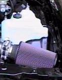
Method 2: K&N Cone Filter
This method bypasses the stock Impala airbox and leaves it intact. It
allows plenty of air into the engine from all sides, not just the small
rectangular slit that the stock air box has. This method also probably allows
more air into the engine than the modified
air box. This method is recommended for those who want high flow and don't
mind a non-stock appearance.
Parts Required:
- A conical K&N air filter. K&N P/N RE-0920. About $40.
- A "breather" type filter for the AIR tube that connects to the stock air
box. Purolator P/N 13103(or one similar that fits (I.D. of the hose is
3/4")). K&N also makes several of them: 62-1030 (2"w x 1.5"h, rubber
top), 62-1160 (3"w x 2"h, chrome top), and 62-1070 (3"w x 2"h, rubber top).
They also make a clamp on unit (62-1360, 2"w x 1.5"h) that will clamp right
on to the AIR pump and get rid of the hose completely. About $20 for any of
them.
- A pipe clamp that fits the top of the K&N. $1.
- Remove the air filter housing lid and the air filter.
- Remove the air filter housing lid from the MAF (mass airflow sensor). Be
careful not to damage the MAF as you remove it, and be sure to mark or
remember the correct direction of the MAF.
- Connect the K&N to the MAF using the pipe clamp. It fits inside the
adapter with a little silicon spray. You should not need any hose to connect
the K&N, but a little tape around the end of the MAF will allow you to
clamp it down without cranking on the clamp as much. The filter goes all the
way to the fender and rests on the computer box.
- Connect the breather to the AIR tube and hide it somewhere up underneath
the conical filter. If you get the female version, you can connect it
directly to the air pump and get rid of the hose entirely.
Method 3: Aftermarket Air Intake Systems
Aftermarket air intake systems, along with eliminating
the rectangular baffle, usually either place a K&N
cone on the end of the MAF, or relocate a K&N cone filter underneath
the fenderwell. By relocating the filter, the air intake can draw in cooler
air from outside of the engine compartment.
Parts Required:
- Aftermarket Air Intake Kit. $200 - $350.
Procedure (will vary, for an example only):
- Remove air box lid, air filter, and air box base.
- Drill a 3.5" hole through the fenderwell to a box behind the fender.
- Install a special bracket to hold the computer and to form a passageway
through the hole to the area between the fender and the plastic splash guard
in the wheelwell.
- Relocate compute to top of wheelwell (using bracket).
- Remove the splash guard from the wheelwell (on the outside of the car).
- Install the K&N cone filter to underside of the bracket.
- Connect a special elbow between the MAF and the new bracket. The new
elbow should have a fitting for the AIR hose.
- Reinstall the plastic splash guard in the wheelwell
Back to
the index...
Advantages
Removing the "home plate" baffle on the top of the engine
not only make the engine look better, but also allows more heat to escape from
the engine and reduces turbulance in the intake air stream, providing more
power. Removing the baffle prevents chafing of the wires underneath it,
possibly saving the cost of a new wire harness.
Disadvantages
The baffle is meant to reduce full-throttle noise. You
may experience a "howling" at full throttle.
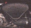
Method 1: Baffle Bypass
This method bypasses the baffle but does not remove it. Total cost is about
$3. This method is recommended if you want to keep the engine looking stock
and don't want to spend much money.
Parts Required:
- A paint can lid. Free.
- Duct tape. $1.
Procedure (from High Performance Chevrolet, January, 1996):
- Loosen and remove the two nuts on top of the "home plate" baffle. They
are 13mm.
- Loosen the clamp that connects the baffle to the intake elbow just in
front of the throttle body.
- Pull up on the baffle and remove it. You may have to "wiggle" it to
remove it. Leave the clamp in place.
- Wrap the paint can lid in duct tape until it can be firmly
wedged inside of the opening on the baffle. The flat part of the lid should
be flush with the bottom lip of the opening.
- Reinstall the baffle.
Method 2: Plugging the Stock Elbow
This method totally removes the baffle. The hole in the intake elbow is
plugged with a pipe cap. Total cost is about $5. The end result looks fairly
OEM. This method is recommended if you want the functional benefits of
removing the baffle and plugging the elbow, but want to keep costs down. Note
that the Callaway air intake system includes hardware to do this, but none of
the other aftermarket air intake systems do.
IMPORTANT: Use of the red Oatey test plug has been
strongly discouraged! Several members have had them disintegrate
under the extreme heat stress in the engine. This can allow unfiltered air to
enter the engine post-MAF, causing a lean condition, along with severe damage
from ingesting parts of the plug itself. If you are using the test plug
(plastic, with a wing nut on top), discontinue use now. Note that
Oatey also makes a metal test plug: this plug can be inserted without fear of
disintegration.
Also note that you need to be sure that the insert that you are
using makes a good seal. Plugs with threads will eventually cut into the elbow
(accelerated by the high heat), and will cause an air leak.
Parts Required:
- A 3" aluminum pipe knockout or "tee" cap. These are available at
hardware stores or some of the home mega-stores. A Nestea cap also fits
pretty well. You could also try to find a 3" O.D. chrome center cap in the
chrome accessories section of your local parts store (Grant Products P/N
5894: Classic Horn Button). The chrome piece looks good with the Razzor
pipe. Other options range from mayonnaise lids to custom milled aluminum
to hockey pucks. You get the idea... About $5.
- A optional can of flat black paint to paint the cap. The engine looks
more OEM if the cap is painted. $2.
- Paint the cap with the flat black paint, if desired.
- Loosen and remove the two nuts on top of the "home plate" baffle. They
are 13mm.
- Loosen the pipe clamp that connects the baffle to the intake elbow just
before the throttle body.
- Pull up on the baffle and remove it. You may have to "wiggle" it to
remove it. Leave the host clamp in place.
- Insert the cap into the hole. It should fit perfectly and should extend
far enough into the hole for the clamp to hold it in place.
- Tighten the clamp.
- Remove the two "towers" that used to hold the baffle in place. Unbolt
them from the black bracket that crosses the intake manifold by using a 6mm
socket or a wrench on the top of them.
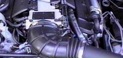
Method 3: Replacing the Stock Elbow with the F-Body 1LE Elbow
This method totally removes the baffle and replaces the stock elbow with
the larger Camaro 1LE (non-airconditioned) intake elbow. The 1LE elbow doesn't
have the hole in top like the Impala does, and doesn't have the hole in the
bottom like the air-conditioned Camaros and Firebirds have. The '94 elbow has
no provision for the vent tube from the OptiSpark distributor, while the '95
has a connector in the top for it. The '94 can be modified to accept the vent
hose by puncturing it on the bottom. The Camaro elbow is wider than the Impala
elbow and can thus flow more air. They are slightly expensive since they
include the MAT sensor. This method is recommended for those looking for
maximum flow into their engines and are willing to pay the price to keep only
GM parts in the engine.
Parts Required:
- A '94 or '95 non-air conditioned 1LE intake elbow. The list price is
$80-$90 (the '94's are cheaper), but some dealers sell them for as much as
$150. P/N 25147210 is the '94 1LE w/o vent nipple ($95.63 retail) and P/N
25147187 is the '95 1LE w/ vent nipple ($155 retail!).
- Loosen and remove the two nuts on top of the "home plate" baffle.
- Loosen the pipe clamp that connects the baffle to the intake elbow just
before the throttle body.
- Pull up on the baffle and remove it. You may have to "wiggle" it to
remove it.
- Remove the rectangular baffle from the front of the elbow. You may have
to remove the air filter cover to do this.
- Remove the stock elbow from the throttle body, removing all sensors and
hoses.
- Replace the stock elbow with the Camaro elbow, reconnecting all sensors
and hoses.
- If the elbow is from a '94, you'll need to pierce it to insert the blue
nipple for the OptiSpark vent. On the first rib from the throttle body,
about 20deg to the driver's side from the bottom, use a drill bit just
smaller than the blue vent tube elbow and bore a hole through the rib. You
can then push the blue vent tube into the hole and hide
"yetanothervacuumtube" from view. You'll need to trim the vacuum tube to
length (about three inches I think). When finished you'll have a factory
looking intake elbow and a hidden distributor vent tube. Be sure to put it
on the side of the elbow, not the bottom, so that moisture won't
enter the distributor.
- The bottom of the elbow has an oval tube protruding from it. That is the
resonator connection, which you'll notice is not opened. Careful work with a
razor knife or razorblade will allow you to cut off the tube and leave a
clean surface on the bottom. A little mistake won't cost you much because
about the only place you can see that spot is from underneath the car. A
pair of tin snips also takes care of the lip quickly.
- Replace the rectangular baffle and the air filter lid.
- Remove the two "towers" that used to hold the baffle in place. Unbolt
them from the black bracket that crosses the intake manifold by using a
socket or a wrench on the top of them.
Back to
the index...
Advantages
Removing the rectangular baffle between the air box and the
intake elbow allows the air to flow with less restriction and turbulance to
the intake, which increases power. It also helps the appearance of the engine
bay.
Disadvantages
The baffle is meant to reduce full-throttle noise. You
may experience a "howling" at full throttle.
Method 1: Baffle Bypass
NOTE: this method has been removed until further notice
from Franklin Poole since the duct
tape can shred, causing engine damage if it is ingested.
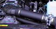
Method 2: Replacing the Baffle with a Pipe
This method replaces the baffle with a piece of chrome exhaust pipe. It
looks much like some of the aftermarket kits that are out there for a lot less
money. This method is recommended for those who don't mind a non-stock looking
engine bay and are on a budget. Note that you can use any sort of pipe you
want for this: chrome exhaust pipe, polished stainless steel, painted PVC
pipe, or whatever. Be creative!
Parts Required:
- A 3.5" chromed exhaust pipe cut to 13". About $20 from Pep Boys.
- A 2"-3" section of 3.5" ID rubber hose. Check with a local heavy truck
supply store for Gates hoses. "GATES Green Strip 3 1/2" I.D. (89 mm)", P/N
24256, seems to work great. You can also get something called a "no hub
coupler" from a hardware store. Basically, any sort of heat- resistant
rubber connector will work fine. About $10 per foot.
- Two pipe clamps to secure the tubing to the MAF and the pipe. $2.
- Originally, the pipe will come tapered on one end (the exit for the
exhaust) and have a 2 1/2" "nipple" on the other to fit into the stanard
exhaust. You will have to cut both of these off so that it is just a
straight piece of chrome pipe. If you can find such a piece without cutting,
then you're better off. You'll need it to be around 13" long.The original
pipe should look something like this:
          ________________________________
          \                               \____
           \                                   |
            \                              ____|
             \____________________________/
- Loosen the clamps on both ends of the baffle.
-
- Remove the baffle. You may need to remove the air filter cover to do
this. Be careful not to damage the MAF (mass airflow sensor) as you remove
the baffle. While you are doing this, make sure you remember (or mark) which
way the MAF faces.
- Clamp the rubber tubing to one side of the chrome tube.
- The other side of the rubber tubing should be clamped to the side of the
MAF that originally was connected to the rectangular baffle. The hose should
fit inside the rubber coupling that used to connect to the resonator.
- Insert the pipe into the intake elbow. Secure the clamp on the elbow so
that it is tight around the pipe.
There is some concern about putting stress on the MAF connector if you are
using the stock airbox. The solution for this is to unmount the airbox from
the top of the PCM and angle it such that when the straight pipe is installed,
the stress on the elbow is relieved.
- Take the air box lid off of the airbox base, remove the filter, and set
them aside.
- Unscrew the Torx head nut/bolt on the fenderwell.
- Look at the airbox; it's actually two pieces consisting of the square
airbox itself and a flat piece underneath that snaps down onto some tabs on
top of the PCM.
- Unsnap that flat piece and pull out the airbox base.
- Take another look at the airbox after it's out of the car. You'll see
two push pins holding the flat piece to the bottom of the box -- one outside
the box, one inside.
- By *carefully* pushing the pin back through the base, remove the push
pin that is outside the box. Leave the one inside the box alone. The airbox
should turn on the one remaining pin effectively providing a pivot point.
- Snap the airbox back into place on the PCM. You should be able to turn
the airbox somewhat.
- Put the filter back in and put the lid back on the airbox.
- Turn the airbox towards the intake elbow as far as possible without
binding anything and measure and install your pipe.
Method 3: Aftermarket Air Intake Systems
All current aftermarket air intake systems for the Impala remove this
rectangular baffle. Instructions for installation will vary. The main
difference between the intake kits are the finish of the parts and the air box
modifications that they include.
Parts Required:
- Aftermarket Air Intake Kit. $200 - $350.
Procedure:
Method 4: Sewer Pipe Substitution
This method uses 3" angles of PVC pipe to substitute for the rectangular
baffle. The advantages to this method is that the angles allow it to line up
with the air box better, and the pipe can be painted and customized in
creative ways. It is also very inexpensive.
Parts Required:
- 2x 3" PVC long-turn street elbows, one inside end and one outside end
- 1x 3" rubber connector
- 1x 3" dia. x 3" long straight piece of PVC pipe
- 2x 3" ring clamps (should come with the connector)
- 1 can PVC purple pipe cleaner
- 1 can PVC cement
- When you are buying the PVC, make sure it is all of the same schedule.
The lowest number is best. This procedure was originally done with schedule
40 PVC.
- Loosen the clamps on both ends of the baffle you are removing.
- Remove the baffle. You may need to remove the air filter cover to do
this. Be careful not to damage the MAF (mass airflow sensor) as you remove
the baffle. While you are doing this, make sure you remember (or mark) which
way the MAF faces.
- Put the big ends of the PVC elbows together using a 3" long piece of the
straight pipe as a connector.
- If you want to, and have the time, you can fill in the joint on the
inside of the pipe with silicone caulk for a more smooth airflow. This is
really difficult, and probably not worth the effort, though. You also might
want to chamfer the inside of the upstream end of the now S-shaped pipe,
again to prevent any sources of turbulence.
- Use the 3" rubber high pressure connector ( you can also use a no-load
connector) to connect the "S" to the MAF with the two steel ring clamps. Cut
about 1" off the end of the connector and cut a small slot on the inside to
match the end protrusion on the lip of the MAF. The chamfered end of the
pipe goes into the other end of the connector (without the notch). The
chamfer eliminates a lip that would have generated some turbulence (
probably not much, but you might as well do things right).
- The other end of the "S" goes into the stock elbow. An added advantage
is theat the end of the pipe extends past the corrugations in the stock
piece, thus aiding in keeping the flow smooth.
- Tighten all of the clamps down and you're ready to go!
Back to
the index...
Go to the full
technical archives...
Go to the technical
archives index...
Go to the Impala SS home
page...
Rob Cheek
rcheek@one.net